Functional Description
ATCA-F120 Installation and Use (6806800D06F
)
98
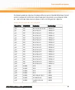
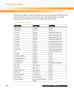
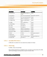
Other sensors available on-board include voltage sensors and sensors which provide particular
status information. A summary of all sensors is given in the following table. For detailed
descriptions refer to the
ATCA-F120: Control via IPMI Programmer’s Reference
.
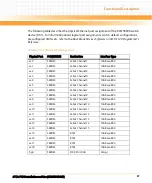
Table 4-7 IPMI Sensors Overview
Sensor Name
Sensor Type
Availability
-48V FEED A
Voltage
Always
-48V FEED B
Voltage
Always
1.0V FIX1
Voltage
While payload powered
1.1V CPU
Voltage
While payload powered
1.25V BIX
Voltage
While payload powered
1.25V FIX2
Voltage
While payload powered
1.2V Base
Voltage
While payload powered
1.8V Base
Voltage
While payload powered
1.8V CPU
Voltage
While payload powered
12V Primary
Voltage
While payload powered
2.5V
Voltage
While payload powered
3.3V MAC
Voltage
Always
3.3V Mgmt AMC B1
Voltage
Always
3.3V Mgmt AMC B4
Voltage
Always
3.3V Mgmt RTM
Voltage
Always
3.3V Payload
Voltage
While payload powered
BIX Temp
Temperature
Always
Boot Error
Boot Error
Always
Bottom Edge Temp
Temperature
Always
CPU Temp
Temperature
Always
Comp Side2 Temp
Temperature
Always
Ejector State
Button / Switch
Always
F120 Active Boot
Emerson-specific Discrete
Digital
Always
Summary of Contents for ATCA-F120
Page 6: ...ATCA F120 Installation and Use 6806800D06F Contents 6 Contents Contents ...
Page 8: ...ATCA F120 Installation and Use 6806800D06F 8 List of Tables ...
Page 10: ...ATCA F120 Installation and Use 6806800D06F 10 List of Figures ...
Page 18: ...ATCA F120 Installation and Use 6806800D06F About this Manual 18 About this Manual ...
Page 24: ...ATCA F120 Installation and Use 6806800D06F Safety Notes 24 ...
Page 120: ...U Boot Firmware ATCA F120 Installation and Use 6806800D06F 120 ...
Page 124: ...Index ATCA F120 Installation and Use 6806800D06F 124 ...
Page 125: ......


