background image

26

.....

Avocent® AutoView™ 2108/2216/3108/3216 Switch Installer/User Guide

by name, EID, or port by choosing one of the buttons. If a device on the list is

unavailable

, it is skipped. Watch

mode views a device unless a conflicting network user blocks the path to that device. If a conflict is detected

in Watch mode (or the device is unavailable), the device to be viewed is skipped.

To add devices to the Scan list:

1.

Activate the OSCAR interface and click

Setup - Scan

to open the

Scan

dialog box.

2.

The dialog box contains a listing of all devices attached to your switch. Click the checkbox to the right of

the device, double-click on the desired entry, or highlight the device, and click the

Add/Remove

button to

toggle the

Scan

checkbox setting. You can select up to 100 devices for inclusion in the Scan list.

NOTE:

Click the

Clear

button to remove all devices from the Scan list.

3.

In the Time field, type the number of seconds (from 3 - 255) to display each device while scanning. The

default is 15 seconds per device.

4.

Click

OK

.

NOTE:

The order in which the devices appear in the

Scan

dialog box is based on the order in which they

were selected. Scanning a single device multiple times during a loop is not supported. Scan time must be

the same for all devices.

Enabling or disabling scan mode

To start the Scan mode:

1.

Activate the OSCAR interface and click

Commands

. The

Commands

dialog box is displayed.

2.

Select

Scan Enable

in the

Commands

dialog box. Scanning will begin.

3.

Click

X

to close the

Commands

dialog box.

To cancel Scan mode:

Select a device if the OSCAR interface is open.

-or-

Move the mouse or press any key on the keyboard if the OSCAR interface is not open. Scanning will stop at

the currently selected device.

-or-

From the

Commands

dialog box, clear the Scan Enable checkbox.

Viewing and disconnecting user connections

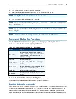
You can view and disconnect users through the

User Status

dialog box. The username (U) and server (S) will

always be displayed when connected to a device (local or remote). You can display either the device name or

EID number to which a user is connected. If there is no user currently connected to a channel, the username

and device fields will be blank.

To view current user connections, activate the OSCAR interface and click

Commands > User Status

to open

the

User Status

dialog box.

Summary of Contents for Avocent AutoView 2108

Page 1: ...Avocent AutoView 2108 2216 3108 3216 Switch Installer User Guide ...

Page 2: ... contain confidential and or proprietary information of Avocent Corporation and its receipt or possession does not convey any right to reproduce disclose its contents or to manufacture or sell anything that it may describe Reproduction disclosure or use without specific authorization from Avocent Corporation is strictly prohibited 2016 Avocent Corporation All rights reserved For important safety i...

Page 3: ...rk 7 Keyboards 7 Quick Setup 7 Connecting the AutoView Switch Hardware 7 Tiering Your Switch Using an IQ Module 9 Adding a tiered switch 11 Adding a tiered legacy switch 12 Configuring Your Switch 15 Setting Up the Built in Web Server 15 Connecting to the OBWI Through a Firewall 15 Verifying Power Status 16 Adjusting Mouse Settings on Target Devices 16 Local OSCAR User Interface 17 Main Dialog Box...

Page 4: ...ring configurations and user databases 33 Property Identity and Location Settings 34 Viewing Version Information 34 Network Settings 35 SNMP Settings 36 Auditing Event Settings 36 Setting Event Destinations 36 Ports Settings Configuring an IQ Adaptor 37 Deleting IQ adaptors 37 Upgrading IQ adaptors 37 Launching a Session 37 General sessions settings 38 Local user account settings 38 Access levels ...

Page 5: ...Appendix B Setup Port Pinouts 53 Appendix C Using Serial IQ Modules 54 Serial IQ module modes 54 Configuring the serial IQ module 54 Creating a serial IQ module macro 55 Using history mode 56 Serial IQ module pinouts 58 Appendix D Sun Advanced Key Emulation 59 Appendix E UTP Cabling 60 UTP copper cabling 60 Wiring standards 60 Cabling installation maintenance and safety tips 61 Appendix F Technica...

Page 6: ...iv Avocent AutoView 2108 2216 3108 3216 Switch Installer User Guide ...

Page 7: ...que device names and Electronic ID EID numbers for each attached device PS 2 and USB IQ modules are available allowing direct KVM connectivity to devices A VMC IQ module is also available The switch is offered with 8 or 16 ARI ports that are used to connect IQ modules to the switch Then utilizing the IQ modules you can attach additional switches to expand your switch system This flexibility allows...

Page 8: ... these screens Virtual media and smart card support The switch allows you to view move or copy data located on local media and smart cards Smart cards are pocket sized cards that store and process information including identification and authentication information to enable access to computers networks and secure rooms or buildings A virtual media or a smart card reader can be connected directly t...

Page 9: ...ccess on the 2108 2216 switch models DSView management software plug in The DSView management software may be used with the switch to allow IT administrators to securely and remotely access and monitor target devices on multiple platforms through a single web based user interface A session may be launched to a device from a single point of access For more information see the Technical Bulletin for...

Page 10: ...and never operate the product in a wet environment If the system gets wet see the appropriate section in your troubleshooting guide or contact your trained service provider Use the product only with approved equipment Allow the product to cool before removing covers or touching internal components Operate the product only from the type of external power source indicated on the electrical ratings l...

Page 11: ...ully Route cables so that they cannot be stepped on or tripped over Be sure that nothing rests on any cables Do not modify power cables or plugs Consult a licensed electrician or your power company for site modifications Always follow your local national wiring rules LAN Related Precautions Do not connect or use during a lightning storm There may be a risk of electrical shock from lightning Never ...

Page 12: ...6 Avocent AutoView 2108 2216 3108 3216 Switch Installer User Guide ...

Page 13: ...e the switch is connected to the network Keyboards A USB keyboard and mouse can be connected to the analog ports of the switch NOTE The switch also supports the use of multiple keyboards and multiple mice on the analog port The use of more than one input device simultaneously however may produce unpredictable results Quick Setup The following is a quick setup list For detailed rack mounting and in...

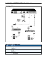
Page 14: ...on Number Description 1 AutoView switch 16 PortModel Shown 7 ACIConnection 2 Power Cord 8 ExternalVirtualMedia USBConnections 3 AnalogUsers 2 9 TargetDevicePorts 4 DigitalUser requirestheRAK key 10 IQ modules 5 LAN Network 11 Servers TargetDevices 6 SETUPConsoleSetupPort Basic Configuration Descriptions ...

Page 15: ...rviceable parts inside the product enclosure Do not open or remove product cover To connect and turn on your switch 1 Connect your VGA monitor and USB keyboard and mouse cables to the appropriately labeled ports 2 Connect one end of a UTP cable 4 pair up to 98 ft 30 m to an available numbered port Connect the other end to an RJ 45 connector of a IQ module 3 Connect a IQ module to the appropriate p...

Page 16: ...e first device you will be connecting to this switch If you are using a USB connection attach the plug from the IQ module to the USB port on the first device you will be connecting to this switch 3 To the RJ 45 connector on the IQ module attach one end of the CAT 5 cabling that will run from your IQ module to the switch 4 Connect the other end of the CAT 5 cable to the desired ARI port on the back...

Page 17: ... tier multiple switches 1 Attach one end of a UTP cable up to 30 meters in length to a device port on the switch 2 Connect the other end of the UTP cable to the ACI port on the back of your tiered switch 3 Connect the devices to your tiered switch 4 Repeat these steps for all the tiered switches you wish to attach to your system NOTE The system automatically merges the two switches All switches co...

Page 18: ...n 4 ACIConnection chainicon Descriptions for Tiering the Switch Adding a tiered legacy switch The following figure illustrates a tiered legacy switch configuration To add a legacy switch optional 1 Mount the switch into your rack Locate a UTP cable up to 30 meters to connect your switch to the legacy switch 2 Attach one end of the UTP cabling to the ARI port on your switch ...

Page 19: ...the IQ module to the legacy switch according to the switch manufacturer s recommendations 5 Repeat steps 1 4 for all the legacy switches you wish to attach to your switch NOTE The primary switch supports only one switch per ARI port or USB port You cannot tier a switch to a tiered switch ...

Page 20: ...View 2108 2216 3108 3216 Switch Installer User Guide Tiering Legacy Switches Number Description 1 LocalUser 2 ARIConnection 3 IQ module 4 PS2Connection 5 TargetDeviceConnection Descriptions for Tiering Legacy Switches ...

Page 21: ...o use the switch UI see Local OSCAR User Interface on page 17 Connecting to the OBWI Through a Firewall For switch installations that use the OBWI for access the following ports must be opened in a firewall if outside access is desired Port Number Function TCP80 Usedfor theinitialdownloadingoftheVideoViewer Theapplianceadministrator canchangethisvalue TCP443 Usedbythewebbrowser interfacefor managi...

Page 22: ...mote user control you must either enable Avocent Module Sync see Mouse Settings for additional information or set the target mouse speed and turn off acceleration For machines running Microsoft Windows Windows NT 2000 XP or Server 2003 use the default USB mouse driver To ensure that the local mouse movement and remote cursor display remain in sync mouse acceleration must be set to none for all use...

Page 23: ...ialog box will appear NOTE If the OSCAR password has been enabled you will be prompted to enter a password before you can launch the OSCAR interface Viewing and selecting ports and devices Use the OSCAR Main dialog box to view configure and control devices in the switch system View your devices by name port or by the unique EID number embedded in each IQ module In the following figure the Port col...

Page 24: ...x Functions Viewing switch system status The status of devices in your system is indicated in the right column of the Main dialog box The following table describes the status symbols Symbol Description Greencircle deviceconnected turnedon andtheIQ moduleisonline Connecteddeviceisturnedoffor isnotoperatingproperly andtheIQ moduleisoffline Connectedswitchisonline Connectedswitchisofflineor notoperat...

Page 25: ...etween the previous and current connections To disconnect from a device Press Print Screen and then Alt 0 zero This leaves the user in a free state with no device selected The status flag on your desktop displays the word Free Soft switching Soft switching is the ability to switch devices using a hotkey sequence You can soft switch to a device by pressing Print Screen and then depending on the met...

Page 26: ...r editingandenablestheleft andrightarrow keystomovethecursor Press EnteragaintoquittheEditmode Print Screen Backspace Togglesbacktopreviousselection Print Screen Pause ImmediatelyturnsonScreenSaver modeandpreventsaccesstothatspecificconsole ifitispassword protected Up Down Arrows Movesthecursor fromlinetolineinlists Right Left Arrows Movesthecursor betweencolumns Wheneditingatextbox thesekeysmovet...

Page 27: ... up your switch to identify devices by unique names Select the other setup features to manage routine tasks for your devices from the OSCAR interface menu The following table lists the functions accessed using each of the buttons in the Setup dialog box To access the OSCAR interface Setup dialog box click Setup on the Main dialog box Feature Purpose Menu ChangetheMaindialogboxlistsortingoptionbyto...

Page 28: ...thods 2 Click OK To set a Screen Delay Time for the OSCAR interface 1 Type in the number of seconds 0 9 to delay the OSCAR interface display after you press Print Screen Enter 0 to launch the OSCAR interface with no delay 2 Click OK Setting a Screen Delay Time enables you to complete a soft switch without the OSCAR interface To perform a soft switch see Soft switching on page 19 Controlling the st...

Page 29: ...aving changes Setting the keyboard country code NOTE Using a keyboard code that supports a language different from that of your switch firmware will cause incorrect keyboard mapping By default the switch sends the US keyboard country code to USB modules attached to devices and the code is applied to the devices when they are turned on or rebooted Codes are then stored in the IQ module Issues may a...

Page 30: ...configuration will be recognized by the switch NOTE When it is initially connected a device will not appear in the Names list until it is turned on Once an initial connection has been made it will appear in the Names list even when turned off To access the OSCAR interface Names dialog box activate the OSCAR interface and click Setup Names NOTE If new IQ modules are discovered by the switch the on ...

Page 31: ...anningintheSetupdialogbox Youmusthaveatleast twodevicesselectedintheSetup ScanListmenuto enabledevicescanning User Status View anddisconnectusers IQ ModuleStatus Displaythecurrentlyavailablefirmwarefor eachtypeof IQ module DisplayVersions View versioninformationfor theswitchaswellasview and upgradefirmwarefor individualIQ modules DisplayConfig View currentconfigurationparameters DeviceReset Re est...

Page 32: ...ices appear in the Scan dialog box is based on the order in which they were selected Scanning a single device multiple times during a loop is not supported Scan time must be the same for all devices Enabling or disabling scan mode To start the Scan mode 1 Activate the OSCAR interface and click Commands The Commands dialog box is displayed 2 Select Scan Enable in the Commands dialog box Scanning wi...

Page 33: ...ation 3 Click Download After the firmware is downloaded the Upgrade dialog box will appear 4 Click the Upgrade button NOTE The switch will reboot when the upgrade is complete To upgrade individual IQ modules 1 Click the IQ button to view individual IQ module version information 2 Select the IQ button to view and click the Version button 3 Click the Load Firmware button 4 Click OK to initiate the u...

Page 34: ...n to the IQ Status dialog box To return an IQ module to factory default status 1 Click IQ in the Version dialog box 2 Select an IQ module then click Decommission 3 Click OK to restore factory defaults You will see the IQ module go offline briefly and return or Click X or press Escape to cancel the operation 4 Click X to close the IQ Select dialog box ...

Page 35: ...7or 8 Yes Yes Yes MicrosoftWindowsServer 2012 Yes Yes Yes MicrosoftWindows2008 Yes Yes Yes RedHatEnterpriseLinux 5 and6 No Yes No CanonicalUbuntu12 04 No Yes No SunSolaris 10and11 No Yes No NovellSUSELinux Enterprise10and11 No Yes No AppleMacOSXTiber 10 4 No Yes No Operating Systems Supported by the OBWI To log in to the switch OBWI 1 Launch a web browser 2 In the address field of the browser ente...

Page 36: ... out or your session has exceeded the inactivity timeout specified by the administrator Using the OBWI After you have been authenticated the user interface appears You may view access and manage your switch as well as specify system settings and change profile settings The following figure shows the user interface window areas Screen descriptions are provided in the following table OBWI Window Num...

Page 37: ...nceSettings Network Networkaddress LAN speed andwebserver ports UnitView ApplianceSettings SNMP Systemdescription SNMPsetting contact read writeandtrapsettings and designationsfor allowedmanagers UnitView ApplianceSettings Auditing EventslistandstatusandSNMPtrapdestinations UnitView ApplianceSettings Ports Status EID name port applicationandinterfacetypefor eachIQ adaptor name port type channels a...

Page 38: ...r province where your organization is located Country the two letter ISO abbreviation for your country Email Address the email address for the Certificate Authority CA to contact 5 Click Generate to create the certificate To upload a new certificate 1 Click the Upload a New Certificate radio button 2 Select the method Filesystem TFTP FTP or HTTP 3 Click Browse to search for the certificate or ente...

Page 39: ...grade Firmware 3 Select one of the following methods to load the firmware file Filesystem TFTP FTP or HTTP NOTE The Filesystem option is only available on the remote OBWI 4 If you selected Filesystem select Browse to specify the location of the firmware upgrade file or If you selected TFTP enter the Server IP Address and Firmware File you wish to load or If you selected FTP or HTTP enter the Serve...

Page 40: ...success screen appears reboot the managed switch to enable the restored configuration Recovering From a Failed Flash Upgrade NOTE You may only recover from a failed Flash upgrade when using IPv4 mode If the green power LED on the front and back panel of the Remote Console switch blinks continuously the Remote Console switch is in recovery mode To recover from a failed Flash upgrade 1 Download the ...

Page 41: ...5 Click Save To configure IPv4 network settings 1 Click the Network tab then click the Address tab to display the IPv4 Settings screen 2 Click the IPv4 button 3 Click to fill or clear the Enable IPv4 checkbox 4 Enter the desired information in the Address Subnet and Gateway fields IPv4 addresses are entered as the xxx xxx xxx xxx dot notation 5 Select either Enabled or Disabled from the DHCP drop ...

Page 42: ...and act as passwords that protect access to the switch The values can be up to 64 characters in length These fields may not be left blank 5 Type the address of up to four management workstations that are allowed to manage this switch in the Allowable Managers fields Alternatively you may leave these fields blank to allow any station to manage the switch 6 Click Save Auditing Event Settings An even...

Page 43: ...are see Tools Rebooting and Upgrading on page 32 or the DSView management software Online Help If issues occur during the normal upgrade process IQ adaptors may also be force upgraded when needed NOTE Check http www avocent com support for firmware upgrade files CAUTION Disconnecting an IQ adaptor during a firmware update or cycling power to the device will render the module inoperable and require...

Page 44: ...he following information is listed about each session Target Device Owner Remote Host Duration and Type General sessions settings To configure general session settings 1 From the side navigation bar select Sessions General The General Session Settings screen appears 2 Select or deselect the Enable Inactivity Timeout checkbox 3 In the Inactivity Timeout field enter the amount of inactive time you w...

Page 45: ...sh to assign to the user account and click Add NOTE User Administrators and Appliance Administrators can access all devices 6 Click Save To delete a user account User Administrator or Appliance Administrator only 1 From the side navigation bar select User Accounts Local Accounts to open the Local User Accounts screen 2 Click the checkbox to the left of each account that you wish to delete then cli...

Page 46: ...ting a virtual media session you can configure the settings that are listed in the following table Setting Description CD ROM DVD ROM AllowsvirtualmediasessionstothefirstdetectedCD ROMor DVD ROM read only drives Enablethis checkboxtoestablishavirtualmediaCD ROMor DVD ROMconnectiontoadevice Disabletoendavirtual mediaCD ROMor DVD ROMconnectiontoadevice MassStorage Allowsvirtualmediasessionstothefirs...

Page 47: ...specified the LDAP default values should be used unless Active Directory has been reconfigured Modifying the default values may cause LDAP authentication server communication errors Configuring LDAP in the User Interface LDAP Overview parameters On the LDAP Overview page in the OBWI you can configure the LDAP authentication priority and the parameters that define LDAP server connection information...

Page 48: ...and dc com Each Search DN value must be separated by a comma The Search Password field is used to authenticate the administrator or user specified in the Search DN field Use the Search Base field to define a starting point from which LDAP searches begin The modifiable default values are dc yourDomainName and dc com For example to define a search base for test com type dc test then dc com Each Sear...

Page 49: ...l attribute the Access Control Attribute field on the LDAP Query Page should be set to info Setting the Notes property to KVM User Admin causes the members of that group to have user administration access to the appliances and target devices that are also members of that same group The Notes property is used to implement the access control attribute The value of the Notes property available in gro...

Page 50: ...ctory If the KVM Appliance Admin value is found the user is given appliance administrator access to the appliance and any attached target devices for Query Mode Appliance or to any selected target device for Query Mode Target Device If the KVM User Admin value is found the user is given user administrator access to the appliance and attached target devices for Query Mode Appliance or to any select...

Page 51: ... on The following is an example of groups defined in Active Directory Active Directory Define Groups Setting up Active Directory for Performing Queries Before you can use any of the querying modes for units you must first make changes to Active Directory so that the selected querying mode can assign the applicable authorization level for the user To set up group queries 1 Log into Windows with adm...

Page 52: ...ibute field and using the Notes property in the group object to implement the access control attribute the value of the Notes attribute in Active Directory may be set to one of the three available access levels KVM User KVM User Admin or KVM Appliance Admin for the group object The members of the group may then access the appliances and target devices at the specified access level Active Sessions ...

Page 53: ... about using the KVM Video Viewer see the KVM Video Viewer Technical Bulletin To open a KVM session 1 From the side navigation bar of the switch web user interface UI click Unit View Target List 2 Click the KVM Session link for the target device you wish to view 3 The KVM Video Viewer launches in a new window ...

Page 54: ...48 Avocent AutoView 2108 2216 3108 3216 Switch Installer User Guide ...
Page 55: ...to access the Console menu interface The terminal may be connected at any time even when the switch is already turned on 2 Once the Console Main Menu is displayed type the number corresponding to Network Configuration and press Enter 3 Type 1 and press Enter to set your network speed For best performance set the switch at the same speed as the Ethernet switch to which it is attached Press Enter to...

Page 56: ... instructed to do so by Technical Support When you are finished viewing the messages press any key to exit this mode Set Change password This menu option allows enabling and disabling of serial port security which locks the serial port with a user defined password Restore factory defaults This menu option will restore all switch options to the default settings Reset appliance This menu option allo...

Page 57: ...e switch trap definitions use the structure described in the following Request For Comments RFCs RFC 1155 SMI Describes the common structures and identification scheme for the definition of management information for use with TCP IP based Internet RFC 1212 Describes the format for producing concise and descriptive MIB modules RFC 1213 MIB Describes the Internet standard MIB II for use with network...

Page 58: ...figurationFileLoaded 21 User DatabaseFileLoaded 22 Traps23 32areUnused 23 32 User Locked 33 User Unlocked 34 IQ moduleUpgradeStarted 35 IQ moduleImageUpgradeResult 36 IQ moduleRestarted 37 VirtualMediaSessionStarted 38 VirtualMediaSessionStopped 39 VirtualMediaSessionTerminated 40 VirtualMediaSessionReserved 41 VirtualMediaSessionUnreserved 42 VirtualMediaSessionMapped 43 VirtualMediaDriveUnmapped...

Page 59: ... pinouts and descriptions are provided in the following figure and table Setup Port Pinouts Pin Number Description Pin Number Description 1 NoConnection 5 TransmitData TXD 2 NoConnection 6 SignalGround SG 3 NoConnection 7 NoConnection 4 ReceiveData RXD 8 NoConnection Console Setup Port Pinout Descriptions ...

Page 60: ...ssing Escape returns you to the previous screen without saving changes Within the Terminal Applications menu s Configuration screen you can modify the following options Baud Rate This option allows you to specify the serial port communications speed Available options are 300 1200 2400 9600 19 200 34 800 57 600 or 115 200 bps The default value is 9600 Parity This option allows you to specify the co...

Page 61: ...e the key combination that makes the Terminal Application menu s Configuration screen appear The default key sequence is Ctrl F8 On Line Key Sequence This option allows you to define the key sequence that displays the On Line mode The default key sequence is Ctrl F10 Help Key Sequence This option allows you to define the key combination that displays the Help System screen The default key sequence...

Page 62: ...ed press Enter to return to the previous screen Using history mode History mode allows you to examine the contents of the history buffer which contains the events that have occurred The serial IQ module maintains a buffer containing 240 lines minimum or 10 screens of output When the history buffer is full it will add new lines at the bottom of the buffer and delete the oldest lines at the top of t...

Page 63: ...uffer If you choose this option a warning screen will appear Press Enter to delete the history buffer or Escape to cancel the action The previous screen will reappear 3 When finished press Ctrl F10 to exit History mode and return to On Line mode ...

Page 64: ...1 DCD DataCarrier Detect OutofSRL DTR DataTerminalReady 2 RXD ReceiveData OutofSRL TXD TransmitData 3 TXD TransmitData IntoSRL RXD ReceiveData 4 DTR DataTerminalReady IntoSRL DSR DataSetReady 5 GND SignalGround N A GND SignalGround 6 DSR DataSetReady OutofSRL DTR DataTerminalReady 7 RTS RequesttoSend IntoSRL CTS Clear toSend 8 CTS Clear toSend OutofSRL RTS RequesttoSend 9 N C NotConnected N A N C ...

Page 65: ...ey combinations will work with the USB USB2 and VMC IQ modules and Avocent USB USB2 and VMC IQ modules With the exception of F12 these key combinations are not recognized by Microsoft Windows Using F12 performs a Windows key press When finished press and hold Ctrl Shift Alt and then press the Scroll Lock key to toggle Sun Advanced Key Emulation mode off Compose Application 1 Compose keypad Power F...

Page 66: ...immunity from the infiltration of unwanted interference CAT 5 cable is generally used for networks running at 10 or 100 Mbps CAT 5E enhanced cable has the same characteristics as CAT 5 but is manufactured to somewhat more stringent standards CAT 6 cable is manufactured to tighter requirements than CAT 5E cable CAT 6 has higher measured frequency ranges and significantly better performance requirem...

Page 67: ...nt Keep the UTP cable as far away as possible from potential sources of EMI such as electrical cables transformers and light fixtures Do not tie the cables to electrical conduits or lay the cables on electrical fixtures Always test every installed segment with a cable tester Toning alone is not an acceptable test Always install jacks so as to prevent dust and other contaminants from settling on th...

Page 68: ...600x1200 60Hz Widescreen 800x500 60Hz 1024x640 60Hz 1280x800 60Hz 1440x900 60Hz 1680x1050 60Hz TargetResolutions Standard 1024x768 60Hz preferred 1280x1024 60Hz preferred 1600x1200 60Hz preferred Widescreen 1280x800 60Hz preferred 1680x1050 60Hz preferred SupportedCabling 4 pair UTP 30metersmaximumlength Dimensions FormFactor 1U or 0U rackmount Dimensions 1 70x 17 00x 9 42inches 4 32x 43 18x 23 93...

Page 69: ...aximum 20W AmbientAtmosphericConditionRatings Temperature Operating 32to122degreesFahrenheit 0to50degreesCelsius Non operating 4to158degreesFahrenheit 20to70degreesCelsius Humidity Operating 20 to80 relativehumidity RH non condensing Non operating 5 to95 relativehumidity RH 38 7degreesCelsiusmaximumwetbulb temperature SafetyandEMC Approvals SafetyandEMC certificationsfor thisproductareobtainedunde...

Page 70: ...64 Avocent AutoView 2108 2216 3108 3216 Switch Installer User Guide ...

Page 71: ...uct check the pertinent section of this manual to see if the issue can be resolved by following outlined procedures For additional assistance visit www avocent com support Avocent Community Support Site To search product knowledge content visit community emerson com networkpower support avocent ...

Page 72: ...smart infrastructure technologies Emerson Network Power provides innovative data center infrastructure management solutions that bridge the gap between IT and facility management and deliver efficiency and uncompromised availability regardless of capacity demands Our solutions are supported globally by local Emerson Network Power service technicians Learn more about Emerson Network Power products ...

Reviews: