Installation, Operation and Maintenance Manual
DOC.IOM.RG.US Rev. 11
November 2021
15
Section 8: Instructions for the SW-4 Limit Switch
Instructions for the SW-4 Limit Switch
Section 8: Instructions for the SW-4 Limit Switch
NOTE:
In hazardous locations, install sealing fitting(s) in accordance with local regulations and national code.
Secure ground wire(s) to ground screw. Ensure that all wires are free of strain and located to clear cover.
NOTE:
Operator stops must be set for valve travel before attempting adjustments.
Determine operator/valve position (open/closed position) before making adjustments.
A. Installation
Refer to
SW-4 Series Limit Switch Installation Procedure
(Document Number: Mod R40).
B. Adjustments
Refer to
SW-4 Series Limit Switch Adjustment Procedure
(Document Number: RAP R61).
NOTE:
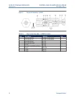
Limit switch is wired as per wiring diagram.
C.
Sensitivity Adjustment
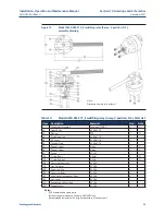
Sensitivity is normally factory set. To adjust, turn trigger screw (13) out to advance and
lengthen signal. Turn in to shorten and delay. Use 0.001" feeler (gap) gauge to ensure no
switch lever contact with switch body.
D.
Microswitch Replacement
1.
Remove electrical power supply before removing cover.
2.
Rotate cam shaft to intermediate (microswitches unactuated) position.
3.
Remove top plate of switch arrangement.
4.
Note miscroswitch arrangement, number of stacks and spacers for reassembly.
5.
Remove microswitch mounting screws.
6.
Disconnect microswitch wires noting wire connections for reassembly.
7.
Install new microswitch.
8.
Connect wires per previous arrangement.
9.
Re-install top plate of switch arrangement.
10.
Rotate cam shaft back to normal position, install cover and restore power.
!
CAUTION
Ensure cover joint threads and o-ring are free of debris and lubricated before replacing cover.
In hazardous locations, keep cover tightly closed while circuits are alive.

