November 2021
Installation, Operation and Maintenance Manual
DOC.IOM.RG.US Rev. 11
22
Section 12: Operator Assembly
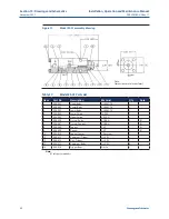
Operator Assembly
Section 12: Operator Assembly
NOTE:
Gas/hydraulic tanks should be drained and flushed if fluid is contaminated with scale, rust,
particulates, water, foam, or etc. Flush only with hydraulic fluid. Refill with filtered fluid.
A.
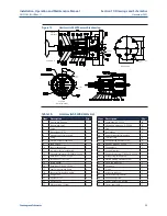
Drive case assembly
1.
Install drive rod guides and lubricate with petroleum jelly.
2.
When valve stem is in horizontal position, install lower yoke bushing and upper
yoke bushing onto yoke. Lubricate with grease.
3.
When valve stem is in vertical position, install upper yoke bushing and o-ring in
drive case cover, and lower yoke bushing in drive case. Lubricate with grease.
4.
Install yoke into drive case.
5.
Install drive rod into drive case.
6.
Install drive rollers in yoke slots, drive pin through drive rod and rollers, snap rings
to retain. Lubricate with petroleum grease. (Series 3 and Series 6 drive pin with its
lower snap ring is installed through access hole in bottom of drive case).
NOTE:
Check that snap rings are seated.
7.
Install drive case cover using sealant around perimeter inside bolt pattern to make
it
weather tight. Torque bolts to specification.
8.
Re-install tanks with handpump and manifold assembly.
B.
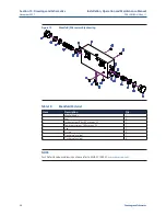
Cylinder assembly
1.
Install drive rod seal in cylinder plate and slide cylinder plate over drive rod into
position with port in correct orientation.
2.
Install, tighten, and TORQUE cylinder plate bolts.
3.
Install cylinder plate ring(s) and 2 different seals.
4.
Lubricating with hydraulic fluid, install wear ring and replace piston seals on piston
with seal lip facing outwards. Insert into cylinder using tapered compression tool
or install seals one at a time with each groove in turn protruding from cylinder.
Press piston back into cylinder in position to match drive rod position.
5.
Install piston o-ring in piston.
6.
Slide piston/cylinder unit on drive rod against cylinder plate/ring taking care that
parts/seals remain in correct position and alignment. Piston seal faces drive rod.
7.
Apply anaerobic adhesive on threads, install, tighten and Torque piston nut/bolt.
8.
Install stay rods.
9.
Install cylinder o-ring on end cap and install end cap with port in correct orientation.
10.
Install stay rod nuts and tighten evenly; Torque to specification.
11.
Reconnect piping cycle unit with handpump to refill cylinders with fluid. Add fluid
to tanks to obtain correct levels for operator positions.
12.
Hydrostatic test with handpump. Refer to Section 7, step 5.
13.
Replace stem key, yoke cover and gasket, and position flag indicating correct
valve position.

