126
10
19
2
3
3
4
9
7
7
1
4
6
6
130
40
40
1/2 NPT
November 2021
Installation, Operation and Maintenance Manual
DOC.IOM.RG.US Rev. 11
26
Section 15: Drawings and Schematics
Drawings and Schematics
Section 15: Drawings and Schematics
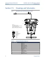
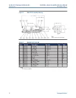
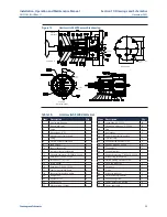
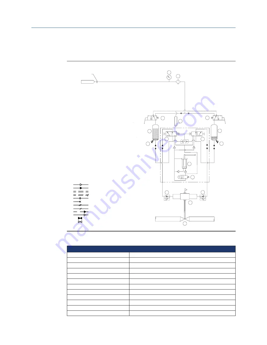
Figure 7
Gas/Hydraulic operator with two way manual schematic
SUPPLY
Close
Open
PIPELINE
Legend:
Power gas
Hydraulic
Electrical
To terminal enclosure
Field connection
Plugged port
Signal
Instrument
Return
Vent
Closed
Open
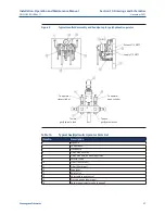
Table 11.
Gas/Hydraulic Operator Component
List of components
1
Operator
2
Line valve
3
Gas/hydraulic tank
4
3-way valve, manual
6
Selector valve
7
Speed control valve
9
Handpump
10
Filter
19
Pressure gauge
40
Bleed/Drain valve
126
Vent tube
130
Manual relief valve
Operation:
- Shown with line valve open
- Press and hold respective lever (4) to close or
open line valve with power gas
- Push the respective knob of selector valve on
handpump to close or open with handpump

