Installation, Operation and Maintenance Manual
DOC.IOM.RG.US Rev. 11
November 2021
35
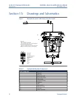
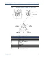
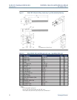
Section 15: Drawings and Schematics
Drawings and Schematics
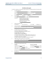
Field Service Request
To assist in providing service/assistance with your equipment, the following information is requested:
A. Contact/Responsible
Name
Company
Position
Site/Project Identification
Phone
Fax
Pager
B.
Valve Operator
Rotary
Linear/Gate
Model
Serial Number
Application:
Mainline Block/Linebreak ESD
Mainline Valve Station Bypass
Unit Suction/Discharge Block
Meter Station Shut In/H
2
S Shut In
PIG Launcher/Receiver
C.
Problem Identified During:
Installation
Commissioning
Operation
Maintenance
D.
Problem Identified as:
(If operator/valve travel is open/closed fully or partially, how far?)
E.
Checklist for often-overlooked causes
Tank fluid levels are correct for operation
Power gas of sufficient pressure and flow is present
ESD/Linebreak system is reset
Operator travels fully and smoothly
Speed controls are more than 25% open
Correctly mounted on valve, ie. valve open/operator open/stops sets
Exhausts not restricted or vented to header system with backpressure
All relays and solenoids are switching
Confirm if signals are being applied and removed as required
F.
Identify Component(s) that may cause the problem
List any adjustments that were made by others
G.
Conditions under which problem occurs
Flowline
Operator Gas Supply
Pipeline Pressure
psi (kPa)
From Pipeline
psi (kPa)
Differential Across Valve
psi (kPa)
From Fuel Gas Line
psi (kPa)
Pipeline Rate of Drop
psi (kPa)/minute
Other/Weather
H. Requirements

