Installation, Operation and Maintenance Manual
DOC.IOM.RG.US Rev. 11
November 2021
9
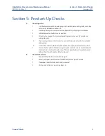
Section 5: Prestart-Up Checks
Prestart-Up Checks
Section 5: Prestart-Up Checks
A.
Check Operator
1.
Unit has been mounted on valve properly. Gear flange mounting bolts, stem key,
set screw(s) installed and secured.
2.
No tubing damaged or accessories dislodged during shipping or installation.
3.
Indicated position confirms valve position.
4.
All control components in normal operating position as per schematic and
wiring diagram.
5.
If removed, yoke cover, limit switch, or end of stroke valve must be re-installed
and secured.
6.
Limit switch shaft centerline aligned with yoke cover/operator stem centerline.
7.
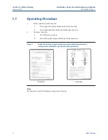
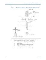
In case of valve stem lubricator, two piece yoke cover set screws are secured and
stem section is centered in yoke cover. There is a gap between top of yoke cover
hub and limit switch adapter. Refer to Figure 3.
B.
Check Connections
1.
Pneumatic/hydraulic connections are tight.
2.
Power gas/signal gas connected to identified ports as per schematic.
3.
If equipped, electrical connections are secured.
4.
Wiring connections as per wiring diagram.


