April 2016
Installation, Operation and Maintenance Manual
RGS011110-2 Rev. 0
7
Section 2: Installation
Installation
2�4
Travel Adjustment
The following instructions are for Left-Hand orientated actuators. For non-standard
models, clockwise and counterclockwise motion will be the inverse of what is
described below. Check the actuator model and orientation before adjusting the
Travel Stops.
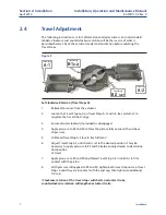
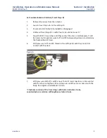
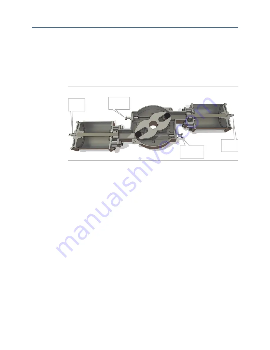
Figure 5
Travel Stop
A-1
Travel Stops
B-1
(x2)
Travel Stops
B-2
(x2)
Travel Stop
A-2
Set Clockwise Rotation (Travel Stops A)
1.
Relieve all pressure from the actuator.
2.
Loosen the Travel Stop nuts on Travel Stops A-1 and A-2. Be careful not to
misplace the travel stop O-rings.
3.
Ensure actuator lockout (if provided) is disengaged.
4.
Apply pressure to P3 and P4 to force the pistons fully outward, then relieve
all pressure.
5.
Unthread Travel Stop A-2 four to five full turns.*
6.
Adjust Travel Stop A-1 until travel is set to the desired position. It may be
necessary to apply pressure to P3 and P4 between adjustments to determine
final position
of travel.
7.
Apply pressure to P3 and P4 and thread Travel Stop A-2 in until it is in firm
contact with the piston.
8.
With pressure still applied to P3 and P4, tighten both travel stop nuts on Travel
Stops A until they are in contact with the end cap, then tighten an additional
1/4 turn.
*Clockwise rotation of the travel stops will shorten actuator stroke,
counterclockwise rotation will lengthen actuator stroke�

