background image

6

To avoid possible fire or shock, do not pinch wires
between the hanger ball/downrod assembly and
hanger bracket.

WARNING

!

Electrical Requirements

If your fan is to replace an existing ceiling light fixture,
turn electricity off at the main fuse box at this time and
remove the existing light fixture.

Your new ceiling fan will require a grounded electrical
supply line of 120 volts AC, 60 Hz, 15 amp circuit.

The outlet box must be securely anchored and
capable of withstanding a load of at least 50 pounds.

Turning off wall switch is not sufficient. To avoid
possible electrical shock, be sure electricity is
turned off at the main fuse box before wiring. All
wiring must be in accordance with National and
Local Codes and the ceiling fan must be properly
grounded as a precaution against possible
electrical shock.

WARNING

!

To reduce the risk of fire, electrical shock, or personal
injury, mount fan to outlet box marked “Acceptable for
Fan Support”, and use screws supplied with outlet box.
Most outlet boxes commonly used for support of light
fixtures are not acceptable for fan support and may
need to be replaced. Consult a qualified electrician if
in doubt.

WARNING

!

U.L. Model No.: CF701
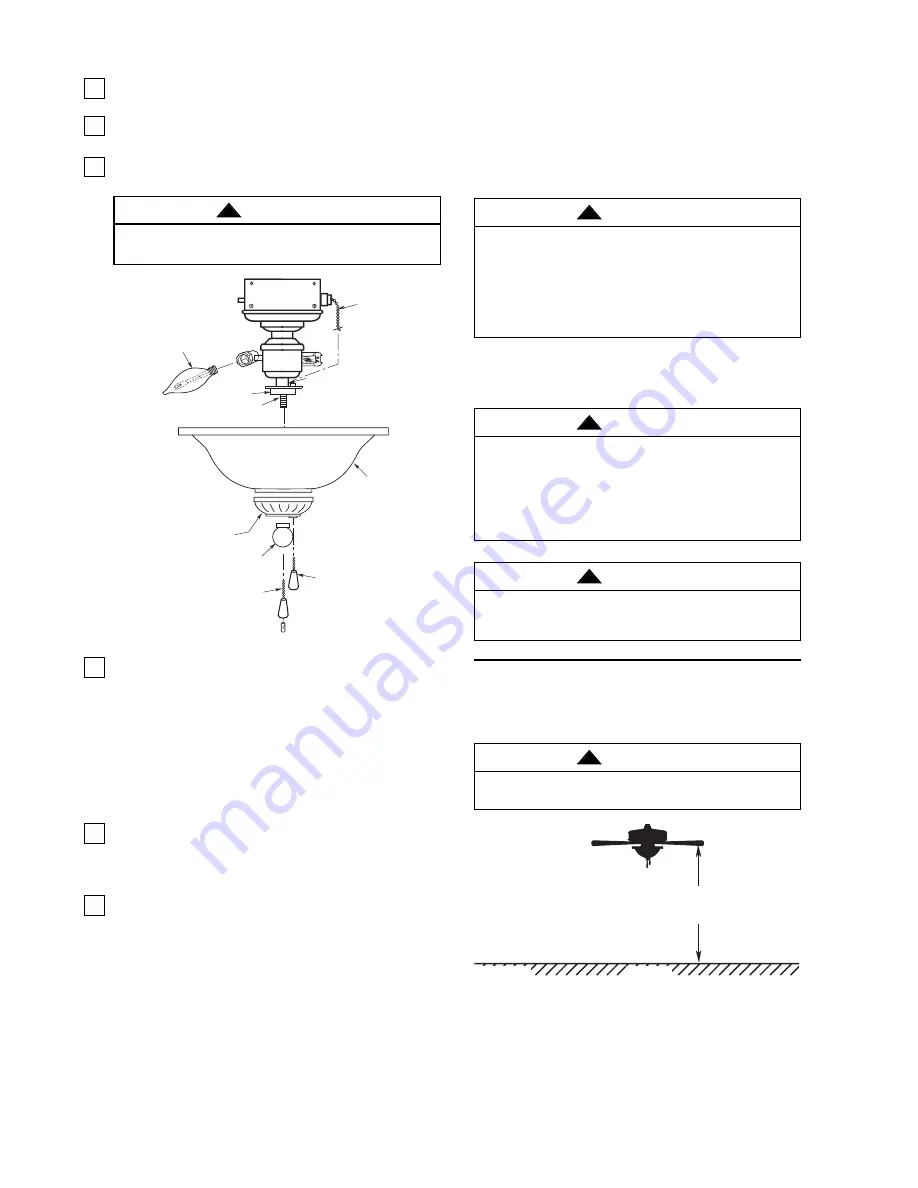
15.

Install two 60-watt (maximum) candelabra base
light bulbs into the light fitter sockets (Figure 8).

16.

Remove the finial nut and outer bowl cap from the
light fitter (Figure 8).

17.

Pass the fan switch chain through the cut-slotted
hole in the bowl cap (Figure 8).

To avoid possible fire hazard, do not exceed wattage
indicated on the fitter.

WARNING

!

THREADED NIPPLE

BOWL CAP

LIGHT FITTER

OUTER BOWL 
CAP

GLASS BOWL

60-WATT 
CANDELABRA 
BASE BULBS (2)

FINIAL NUT

FAN SWITCH
CHAIN

PENDANTS (2)

LIGHT SWITCH
CHAIN

Figure 8

18.

Position the glass bowl over the threaded nipple
and seat bowl on bowl cap (Figure 16). Pass the
fan pull chain through the bushing in the outer
bowl cap and install the cap on the threaded
nipple. Install nut finial finger tight.

CAUTION

Be sure that the fan switch chain does not make
contact with the light bulbs. If necessary
reposition the light fitter to avoid the fan switch
chain from touching the light bulbs.

19.

Install pendants onto light fixture chain and fan
switch chain using couplings provided.

NOTE: It is advisable to periodically check the
tightness of the finial.

20.

You have now completed the assembly of your
new ceiling fan. You can now proceed with
hanging and wiring your fan.

The fan must be hung with at least 7' of clearance
from floor to blades (Figure 9).

WARNING

!

FLOOR

7'

MIN.

Figure 9

Installing The

Hanger Bracket

Summary of Contents for BUILDER UNIPACK CF701BS00

Page 1: ...s of the nearest authorized service center You will be responsible for all insurance freight or other transportation charges to our factory or authorized service center Your Emerson Air Comfort Ceiling Fan should be properly packed to avoid damage in transit since we will not be responsible for any such damage What Is Not Covered The glass globes and light bulbs of your ceiling fan are not covered...

Page 2: ...Acceptable for Fan Support and use the mounting screws provided with the outlet box Most outlet boxes commonly used for support of light fixtures are not acceptable for fan support and may need to be replaced Consult a qualified electrician if in doubt 4 The downrod furnished with the fan provides the minimum recommended floor to fan blade clearance for an 8 foot ceiling 5 The fan must be mounted ...

Page 3: ...ach step As each step is completed place a check mark in the box This will insure that all steps have been completed and will be helpful in finding your place should you be interrupted Before assembling your ceiling fan refer to section on proper method of wiring your fan page 7 If you feel you do not have enough wiring knowledge or experience have your fan installed by a licensed electrician Do n...

Page 4: ...g up on the hanger ball securely tighten the two setscrews in the motor coupling Figure 1 NOTE The setscrews must be properly installed as described above or fan wobble could result 5 The fan comes with blue black and white leads that are 42 long Measure up approximately 6 to 9 inches above top of hanger ball downrod assembly Cut off excess leads and strip back insulation 1 2 inch from end of lead...

Page 5: ...ITCH CUP SWITCH CUP CONNECTOR Figure 4 SPRING LOCKWASHER SCREWS SWITCH CUP CONNECTOR WIRE CONNECTORS WHITE WIRES SWITCH HOUSING ASSEMBLY BLACK WIRE NUT FAN SWITCH CHAIN BLUE WIRE LIGHT FITTER BOWL CAP Figure 5 12 Engage the connector of the switch housing assembly with the motor connector Figure 6 The two connectors are keyed and color coded and must be mated correctly color to color before they c...

Page 6: ...U L Model No CF701 15 Install two 60 watt maximum candelabra base light bulbs into the light fitter sockets Figure 8 16 Remove the finial nut and outer bowl cap from the light fitter Figure 8 17 Pass the fan switch chain through the cut slotted hole in the bowl cap Figure 8 To avoid possible fire hazard do not exceed wattage indicated on the fitter WARNING THREADED NIPPLE BOWL CAP LIGHT FITTER OUT...

Page 7: ...ews supplied with outlet box Most outlet boxes commonly used for support of light fixtures are not acceptable for fan support and may need to be replaced Consult a qualified electrician if in doubt WARNING The outlet box and joist must be securely mounted and capable of supporting at least 50 lbs Use only a U L outlet box listed as Acceptable for Fan Support WARNING OUTLET BOX HANGER BRACKET HANGE...

Page 8: ...ion of the light by gently pulling on the light switch pull chain 3 Check the operation of the fan by gently pulling on the speed control switch pull chain The operation sequence is as follows 1st pull High 2nd pull Medium 4 Your fan is shipped from the factory with the reversing switch positioned to circulate air downward If airflow is desired in opposite direction turn the fan off and wait for t...

Page 9: ...witch position is all the way to one side 2 Fan sounds noisy 1 Blades not attached to fan 1 Attach blades to fan before operating 2 Screws securing fan blade flanges to motor hub 2 Check to make sure the screws which attach the fan are loose flanges to the motor hub are tight WARNING Make sure main power is turned off 3 Wire connectors inside switch housing rattling 3 Check to make sure wire conne...

Page 10: ...763102 ORB 763102 WW 8 Blade Set of 5 763100 13 763100 14 763100 7 Parts Bag Containing 763901 763901 1 763901 2 9 Wire Connector 3 10 Hairpin Clip 1 11 Clevis Pin 1 12 Wood Ball Pendant 2 13 Coupling 2 14 Threaded Stud 8 32 x 1 1 4 2 15 Lockwasher 8 32 2 16 Knurled Knob 8 32 2 17 Screw Flange M6 x 12mm with Lockwasher 11 18 Screw Blade M5 x 6mm 16 19 Wiring Harness 763920 3 763920 2 763920 4 20 F...

Page 11: ...tain all parts have been removed HOW TO ORDER REPAIR PARTS WHEN ORDERING REPAIR PARTS ALWAYS GIVE THE FOLLOWING INFORMATION PART NUMBER PART DESCRIPTION NAME OF ITEM MODEL NUMBER For repair parts phone 1 800 654 3545 7 8 3 2 10 11 9 17 18 14 1 15 16 19 6 21 13 20 12 22 5 13 12 4 ...

Page 12: ...Air Comfort Products DIVISION OF EMERSON ELECTRIC CO 8100 W Florissant St Louis MO 63136 U L Model No CF701 Form No BP7392 Printed in China 03 09 Part No F40BP73920000 ...

Reviews: