background image

3.

Screw the two threaded studs (supplied) into the
tapped holes in the hanger bracket.

4.

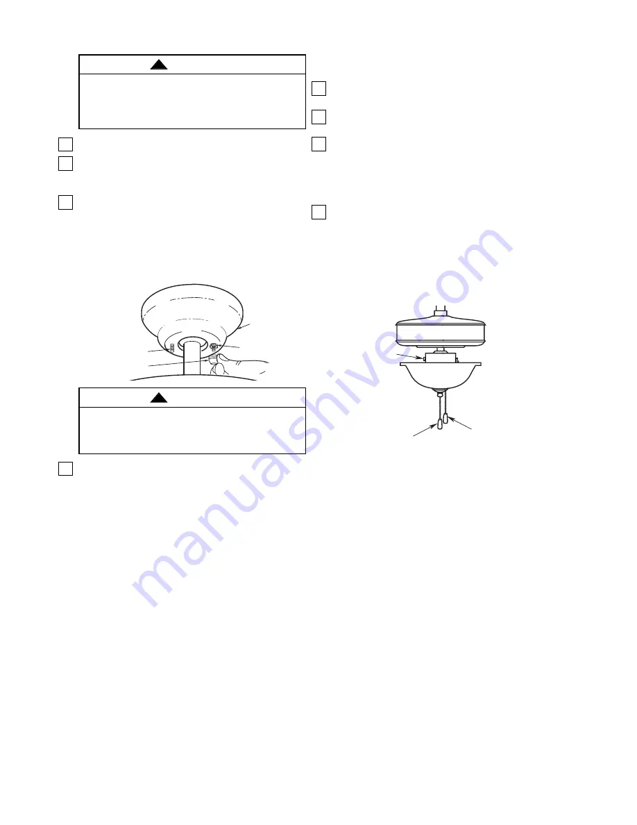
Lift the ceiling cover up to the threaded studs and
turn until studs protrude through the holes in the
ceiling cover (Figure 13).

5.

Secure the ceiling cover in place by sliding
lockwashers over the threaded studs and installing
the two knurled knobs (supplied). (Figure 13.)
Tighten the knurled knobs securely until the ceiling
cover fits snugly against the ceiling and the hole in
the ceiling cover is clear of the downrod. Your fan
is now wired to be turned on and off from the fan
switch.

6.

Cut the 3-speed switch pull chain to a desired
length (optional). Connect the wood pendant
(supplied) to the 3-speed switch pull chain by
sliding the wooden pendant (small hole first) onto
the pull chain. Attach the chain coupler to the end
of the chain and allow the wooden pendant to fall
down over the coupling.

1.

Restore electrical power to the outlet box by turning
the electricity on at the main fuse box.

2.

Check the operation of the light by gently pulling on
the light switch pull chain.

3.

Check the operation of the fan by gently pulling on
the speed control switch pull chain. The operation
sequence is as follows:

1st pull - High

2nd pull - Medium

4.

Your fan is shipped from the factory with the
reversing switch positioned to circulate air
downward. If airflow is desired in opposite
direction, turn the fan off and wait for the blades to
stop turning, then slide the reversing switch to the
opposite position, and turn the fan on again. The
fan blades will turn in the opposite direction and
reverse the airflow.

8

Using Your Ceiling Fan

SPEED CONTROL
PULL CHAIN SWITCH

REVERSING
SWITCH

LIGHT PULL
CHAIN SWITCH

3rd pull - Low

4th pull - OFF

U.L. Model No.: CF701

CEILING COVER

THREADED STUD

KNURLED KNOB

LOCKWASHER

Figure 13

Check to see that all connections are tight, including
ground, and that no bare wire is visible at the wire
connectors, except for the ground wire. Do not
operate fan until blades are in place. Noise and fan
damage could result.

WARNING

!

To avoid possible fire or shock, make sure that the
electrical wires are completely inside the outlet box
and not pinched between the ceiling cover and the
ceiling.

WARNING

!

Summary of Contents for BUILDER UNIPACK CF701BS00

Page 1: ...s of the nearest authorized service center You will be responsible for all insurance freight or other transportation charges to our factory or authorized service center Your Emerson Air Comfort Ceiling Fan should be properly packed to avoid damage in transit since we will not be responsible for any such damage What Is Not Covered The glass globes and light bulbs of your ceiling fan are not covered...

Page 2: ...Acceptable for Fan Support and use the mounting screws provided with the outlet box Most outlet boxes commonly used for support of light fixtures are not acceptable for fan support and may need to be replaced Consult a qualified electrician if in doubt 4 The downrod furnished with the fan provides the minimum recommended floor to fan blade clearance for an 8 foot ceiling 5 The fan must be mounted ...

Page 3: ...ach step As each step is completed place a check mark in the box This will insure that all steps have been completed and will be helpful in finding your place should you be interrupted Before assembling your ceiling fan refer to section on proper method of wiring your fan page 7 If you feel you do not have enough wiring knowledge or experience have your fan installed by a licensed electrician Do n...

Page 4: ...g up on the hanger ball securely tighten the two setscrews in the motor coupling Figure 1 NOTE The setscrews must be properly installed as described above or fan wobble could result 5 The fan comes with blue black and white leads that are 42 long Measure up approximately 6 to 9 inches above top of hanger ball downrod assembly Cut off excess leads and strip back insulation 1 2 inch from end of lead...

Page 5: ...ITCH CUP SWITCH CUP CONNECTOR Figure 4 SPRING LOCKWASHER SCREWS SWITCH CUP CONNECTOR WIRE CONNECTORS WHITE WIRES SWITCH HOUSING ASSEMBLY BLACK WIRE NUT FAN SWITCH CHAIN BLUE WIRE LIGHT FITTER BOWL CAP Figure 5 12 Engage the connector of the switch housing assembly with the motor connector Figure 6 The two connectors are keyed and color coded and must be mated correctly color to color before they c...

Page 6: ...U L Model No CF701 15 Install two 60 watt maximum candelabra base light bulbs into the light fitter sockets Figure 8 16 Remove the finial nut and outer bowl cap from the light fitter Figure 8 17 Pass the fan switch chain through the cut slotted hole in the bowl cap Figure 8 To avoid possible fire hazard do not exceed wattage indicated on the fitter WARNING THREADED NIPPLE BOWL CAP LIGHT FITTER OUT...

Page 7: ...ews supplied with outlet box Most outlet boxes commonly used for support of light fixtures are not acceptable for fan support and may need to be replaced Consult a qualified electrician if in doubt WARNING The outlet box and joist must be securely mounted and capable of supporting at least 50 lbs Use only a U L outlet box listed as Acceptable for Fan Support WARNING OUTLET BOX HANGER BRACKET HANGE...

Page 8: ...ion of the light by gently pulling on the light switch pull chain 3 Check the operation of the fan by gently pulling on the speed control switch pull chain The operation sequence is as follows 1st pull High 2nd pull Medium 4 Your fan is shipped from the factory with the reversing switch positioned to circulate air downward If airflow is desired in opposite direction turn the fan off and wait for t...

Page 9: ...witch position is all the way to one side 2 Fan sounds noisy 1 Blades not attached to fan 1 Attach blades to fan before operating 2 Screws securing fan blade flanges to motor hub 2 Check to make sure the screws which attach the fan are loose flanges to the motor hub are tight WARNING Make sure main power is turned off 3 Wire connectors inside switch housing rattling 3 Check to make sure wire conne...

Page 10: ...763102 ORB 763102 WW 8 Blade Set of 5 763100 13 763100 14 763100 7 Parts Bag Containing 763901 763901 1 763901 2 9 Wire Connector 3 10 Hairpin Clip 1 11 Clevis Pin 1 12 Wood Ball Pendant 2 13 Coupling 2 14 Threaded Stud 8 32 x 1 1 4 2 15 Lockwasher 8 32 2 16 Knurled Knob 8 32 2 17 Screw Flange M6 x 12mm with Lockwasher 11 18 Screw Blade M5 x 6mm 16 19 Wiring Harness 763920 3 763920 2 763920 4 20 F...

Page 11: ...tain all parts have been removed HOW TO ORDER REPAIR PARTS WHEN ORDERING REPAIR PARTS ALWAYS GIVE THE FOLLOWING INFORMATION PART NUMBER PART DESCRIPTION NAME OF ITEM MODEL NUMBER For repair parts phone 1 800 654 3545 7 8 3 2 10 11 9 17 18 14 1 15 16 19 6 21 13 20 12 22 5 13 12 4 ...

Page 12: ...Air Comfort Products DIVISION OF EMERSON ELECTRIC CO 8100 W Florissant St Louis MO 63136 U L Model No CF701 Form No BP7392 Printed in China 03 09 Part No F40BP73920000 ...

Reviews: