© 2020 Emerson. All rights reserved.
Before installation, these instructions must be read carefully and understood.
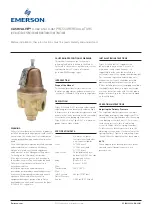
CASH VALVE™
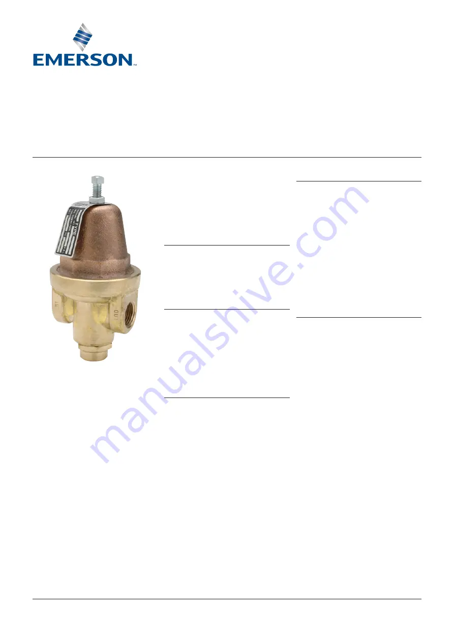
A-360 AND A-361 PRESSURE REGULATORS
INSTALLATION, OPERATION AND MAINTENANCE INSTRUCTIONS
DESCRIPTION
Types A-360 and A-361 pressure reducing and
regulating valves automatically reduce a high
inlet pressure to a lower delivery pressure and
maintain that lower pressure within reasonably
close limits, even during high flow rates.
Type A-360 is 2-way; Type A-361 is 4-way with
gauge taps on sides of body.
SPECIFICATION DATA
Service:
Air, water, oil, gases
(except steam) and other
non-corrosive liquids
Sizes:
¼" (6.35 mm),
⅜" (9.53 mm), and
½" (12.7 mm)
Connections:
Threaded female inlet
and outlet, A-361 has side
gauge connections
Body:
Brass - A-360
Bronze - A-361
Max.
Temperature:
180°F (82°C)
Max.
Inlet Pressure:
400 psi (27.57 bar)
Outlet Pressure
Range:
0-250 psi (0-17.23 bar)
INSTALLATION INSTRUCTIONS
Types A-360 and A-361 regulators can
be installed in any position. For ease of
maintenance and repair however, it is
suggested that the valve be installed in a
horizontal line with the spring chamber upright.
For convenient operation and maintenance,
manual shut-off valves should be installed
upstream and downstream from the valve.
Before installing the valve, the piping should be
thoroughly flushed out to remove any foreign
material. Install the valve with the inlet pipe in
proper relationship to the flow arrow stamped
on the valve body.
OPERATING INSTRUCTIONS
Adjusting the Delivery Pressure
The regulator's delivery pressure setting is
adjusted by turning the adjusting screw (1) at
the top of the spring chamber after loosening
the adjusting screw lock nut (2). To increase
the delivery pressure, turn the adjusting
screw clockwise (into the spring chamber).
To decrease the delivery pressure, turn the
adjusting screw counter-clockwise (out of the
spring chamber). Tighten the adjusting screw
lock nut after the adjustment has been made.
NOTE:
When adjusting the delivery pressure, draw
flow and shutoff downstream to check
pressure set.
VCIOM-14994-EN 22/01
WARNING
Failure to follow these instructions or to properly
install and maintain this equipment could result in
an explosion, fire and/or chemical contamination
causing property damage and personal injury or
death.
Cash Valve regulators must be installed, operated
and maintained in accordance with federal,
state and local codes, rules and regulations
and Emerson Process Management Regulator
Technologies, Inc. (Emerson) instructions.
If the regulator vents gas or a leak develops in
the system, service to the unit may be required.
Failure to correct trouble could result in a
hazardous condition.
Installation, operation and maintenance
procedures performed by unqualified personnel
may result in improper adjustment and unsafe
operation. Either condition may result in
equipment damage or personal injury. Only a
qualified person shall install or service the types
A-360 or A-361 regulators.
CALIFORNIA PROPOSITION 65 WARNING
This product can expose you to chemicals
including lead, which is known to the State of
California to cause cancer, birth defects, or other
reproductive harm. For more information,
go to www.P65Warnings.ca.gov
INTRODUCTION
Scope of the Manual
This manual provides instructions for the
installation, adjustment, and maintenance for
the types A-360 and A-361 pressure regulators.


