2
CASH VALVE™
A-360 AND A-361 PRESSURE REGULATORS
INSTALLATION, OPERATION AND MAINTENANCE INSTRUCTIONS
MAINTENANCE INSTRUCTIONS
The following procedures are provided for
servicing the recommended spare parts for the
Types A-360 and A-361 regulators. Repair parts
can easily be installed without removing the
regulator from the line.
CAUTION
Before attempting to replace any spare parts be
sure to shut off all pressure connections to the
valve. With the valve closed, however, system
pressure could still be locked between the shut
off valve and the inlet and/or outlet sides of the
regulator. Before proceeding with any valve
service be certain to relieve the pressure from
BOTH sides of the regulator.
Servicing Diaphragm(s), Top O-Ring, and
Pressure Spring
1. Loosen the lock nut and turn the adjusting
screw counterclockwise until the pressure
spring is no longer under tension. When
reassembling, run the adjusting screw down
until the lock nut almost touches the spring
chamber. This will give you approximately
the same set as before disassembly.
2. Remove the spring chamber from the
body. When reassembling, torque to
50-60 ft-lbs (67.8-81.3 N•m).
REPAIR PARTS INFORMATION
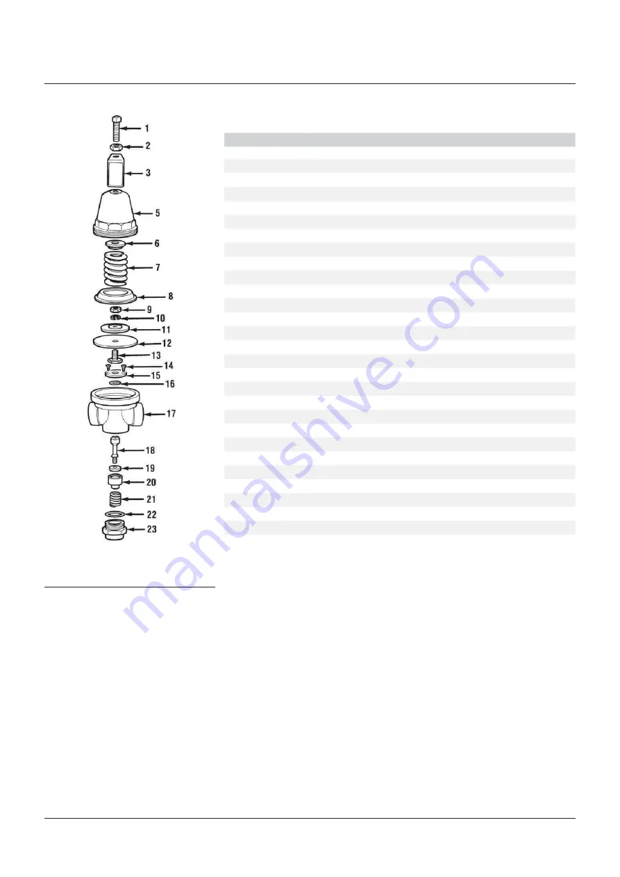
Refer to the regulator exploded view for parts identification.
Item No. Description
Material
Quantity
1
Adjusting Screw (Square Head)
Steel
1
1
+
Adjusting Screw (T-Handle) Set
Brass
1
2
Lock Nut (Hex for Sq. Hd. Screw)
Steel
1
2+
Lock Nut (Hex for T-Handle)
Steel
1
2+
Lock Nut (Wing for Panel Mounting)
Steel
1
3
Identification Tag
Aluminum
1
4
Bushing (for Panel Mounting only)
Brass
1
5
Spring Chamber (for Sq. Hd. Screw)
Brass
1
5+
Spring Chamber (for T-Handle)
Brass
1
5+
Spring Chamber (for Panel Mounting)
Brass
1
6
Spring Button
Brass
1
7
Pressure Spring (see Ranges chart)
Stainless steel
1
8
Diaphragm Stop
Brass
1
9
Pressure Plate Nut
Steel
1
10
Lock Washer
Steel
1
11
Pressure Plate
Brass
1
12*
Diaphragm
Neoprene
1
13
Pusher Post Button (A-360, A-361)
Brass
1
14
Retainer Plate Screws
Brass
2
15
Retainer Plate
Brass
1
16*
O-Ring (Top)
Buna-N
(1)
1
17
Body (A-360 2 Way)
Brass
1
17+
Body (A-361 4 Way)
Brass
1
18*
Pusher Post (A-360, A-361)
Stainless steel
1
19*
Seat Disk
Buna-N
(1)
1
20*
Piston
Brass
1
21
Piston Spring
Stainless steel
1
22*
O-Ring (Bottom)
Buna-N
(1)
1
23
Bottom Plug
Brass
1
* Recommended Spare Parts
+ Not pictured
1 Depending on construction. Seat Material also available in Viton and Teflon. Seat Material
selection determines O-ring material.
3. Remove the spring button, pressure
spring, diaphragm stop, and diaphragm
subassembly. When reassembling,
torque diaphragm nut to approximately
75 in-lbs (8.48 N•m).
4. If the top o-ring is to be serviced, remove
the two retainer plate screws and remove
the retainer plate and top o-ring. Lubricate
top o-ring with Dow Corning Molykote 111 or
equivalent before installing.
5. Inspect all parts for wear and damage and
replace if necessary. Reassemble parts
in reverse order. DO NOT OVERTIGHTEN.
Follow the Operation Instructions to reset
the delivery pressure.


