background image

How To Put Your Ceiling Fan Together

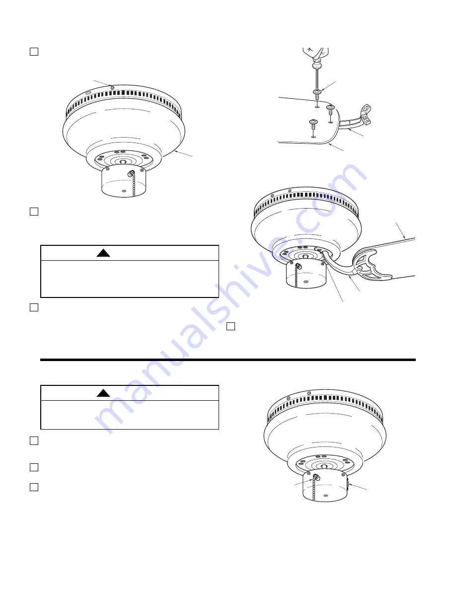
1. Align the four holes in the fan housing with the

holes in the mounting plate and install four 3/16-24
x 3/8" screws (Figure 6).

2. Mount the blade flanges to the fan blades using

three 3/16-24 x 9/32" washer head screws per
blade (supplied) (Figure 7). Repeat for four
remaining blades.

3. Attach one blade assembly to the motor using two

1/4-20 x 1/2" phillips head screws (supplied)
(Figure 8). Make sure the screws are tightened
securely. Repeat this procedure for the other four
blade assemblies.

NOTE: Take care not to scratch the fan housing
when installing the blade assemblies.

4. You have now completed the assembly of your new

ceiling fan.

1/4-20 x 1/2" SCREWS (2)

BLADE FLANGE

BLADE

Figure 8

BLADE
FLANGE

FAN BLADE

3/16-24 x 9/32" WASHER 
HEAD SCREWS (3) 

Figure 7

FAN
HOUSING

3/16-24 x 3/8" SCREW

Figure 6

Using Your Ceiling Fan

1. Restore electrical power to the electrical box by

turning the electricity on at the main fuse box or
circuit breaker panel.

2. Check the operation of the fan by gently pulling on

the pull chain switch.

3. All fans are shipped from the factory with the re-

versing switch positioned to circulate air downward.
If airflow is desired in opposite direction, turn your
fan off and wait for the blades to stop turning, then
slide the reversing switch to opposite position, and
turn fan on again. The fan blades will turn in the
opposite direction and reverse the airflow.

Your fan model is equipped with a 4-position,
3-speed pull chain switch. The operating sequence
is as follows:

REVERSING
SWITCH

SPEED
CONTROL SWITCH

Figure 9

6

THREE SPEED:
1st Pull – High
2nd Pull – Medium
3rd Pull – Low
4th Pull – OFF

To reduce the risk of personal injury, do not bend the
blade flange when installing the blade flanges,
balancing the blades or cleaning the fan. Do not
insert foreign objects in between rotating fan blades.

WARNING

!

To reduce the risk of fire or electrical shock, do not
use this fan with any solid-state speed control
device.

WARNING

!

Summary of Contents for CF804SAB

Page 1: ...e responsible for all insurance freight or other transportation charges to our factory or authorized service center Your Emerson Air Comfort Ceiling Fan should be properly packed to avoid damage in transit since we will not be responsible for any such damage What Is Not Covered The glass globes and light bulbs of your ceiling fan are not covered by this warranty This warranty also does not cover a...

Page 2: ...let boxes listed as acceptable for fan support and use the mounting screws provided with the outlet box Most outlet boxes commonly used for support of light fixtures are not acceptable for fan support and may need to be replaced Consult a qualified electrician if in doubt 4 The downrod furnished with the fan proves the minimum recommended floor to fan blade clearance for an 8 foot ceiling 5 The fa...

Page 3: ... being lost If any parts are missing contact your local retailer or catalog outlet for replacement before proceeding 2 Remove the fan assembly from the protective plastic bag Place the fan assembly into the upper foam pad with the lead wires up Unpacking Instructions For your convenience check off boxes are provide next to each step As each step is completed place a check mark in the box This will...

Page 4: ...AN MOTOR ASSEMBLY MOTOR BRACKET SUPPLY WIRE LEADS THREADED STUDS RUBBER WASHER Figure 3 To reduce the risk of fire electric shock or personal injury mount fan to outlet box marked acceptable for fan support and use screws supplied with outlet box Most outlet boxes commonly used for support of light fixtures are not acceptable for fan support and may need to be replaced Consult a qualified electric...

Page 5: ...ire and blue wire to the supply black hot wire using a listed wire connector Figure 5 Your fan is now wired to be turned on and off from the fan switch After connections have been made turn leads upward and carefully push leads into the outlet box with the white and green leads on one side of the outlet box and the black and blue leads on the other side of the outlet box 4 Connect the wood ball wi...

Page 6: ...he electrical box by turning the electricity on at the main fuse box or circuit breaker panel 2 Check the operation of the fan by gently pulling on the pull chain switch 3 All fans are shipped from the factory with the re versing switch positioned to circulate air downward If airflow is desired in opposite direction turn your fan off and wait for the blades to stop turning then slide the reversing...

Page 7: ...according to the procedure in the section on How to Put Your Ceiling Fan Together 3 Mounting plate and or ceiling outlet 3 Tighten the mounting plate screws to box is not securely fastened the outlet box and or secure outlet box 4 Fan blades out of balance 4 Interchanging an adjacent side by side blade pair can redistribute the weight and result in smoother operation Maintenance IMPORTANT CARE INS...

Page 8: ...1555 761555 1 761555 761555 3 761555 1 761555 2 761555 761555 1 761555 Hanging Hardware Pull Chain Ball 5 Harness Wiring 761543 1 761543 761543 2 761543 1 761543 3 761543 2 761529 761529 761529 761529 Owner s Manual BP7192 5 BP7192 5 BP7192 5 BP7192 5 BP7192 5 BP7192 5 BP7192 5 BP7192 5 BP7192 5 BP7192 5 3 1 5 2 Printed in Taiwan Part No F40BP71920005 12 00 Form No BP7192 5 Before discarding packa...

Reviews: