background image

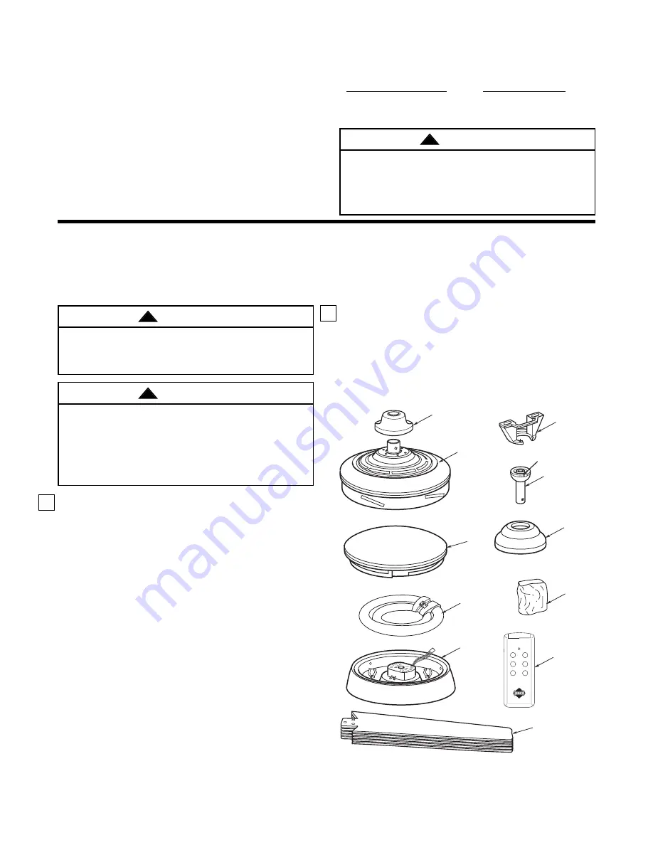
1. Check to see that you have received the following

parts:

NOTE: If you are uncertain of part description,
refer to exploded view illustration.

a. Fan motor assembly
b. One lower housing assembly
c. One ceiling cover
d. Five fan blades
e. One hanger ball/downrod assembly
f. One hanger bracket
g. One glass globe
h. One fan/light control
i. One coupler cover
j. One fluorescent twin-tube 40W lamp
k. One loose parts bag containing:

1. Sixteen 3/16-24 x 1/2” slotted Phillips 

washer head blade screws

2. Three wire connectors
3. Two 1-1/4" threaded studs
4. Two lockwashers
5. Two knurled knobs
6. One clevis pin
7. One hairpin clip

NOTE: Place the parts from the loose parts bags
in a small container to keep them from being lost.
If any parts are missing, contact your local retailer
or catalog outlet for replacement before
proceeding.

This Manual Is Designed to Make it as Easy as Possible for You to

Assemble, Install, Operate and Maintain Your Ceiling Fan

Tools Needed for Assembly

One Phillips head screwdriver

One stepladder

One 1/4” blade screwdriver

One wire stripper

Three wire connectors (supplied)
One 3/16” hex wrench (supplied)

MATERIALS

Wiring outlet box and box connectors must be of type
required by the local code. The minimum wire would
be a 3-conductor (2-wire with ground) of the following
size:

3

Unpacking Instructions

For your convenience, check-off boxes are provided next to each step. As each step is
completed, place a check mark in the box. This will insure that all steps have been
completed and will be helpful in finding your place should you be interrupted.

2. Remove the fan assembly from the protective

plastic bag. Place the fan assembly into the upper
foam pad with the top of the motor facing up.

The upper foam pad serves as a holder for the fan
during the first stages of assembly.

FAN
ASSEMBLY

COUPLER
COVER

LOWER
HOUSING
ASSEMBLY

FLOURESCENT
TWIN-TUBE
40W LAMP

HANGER
BRACKET

GLASS
BOWL

FAN BLADES

FAN/LIGHT
CONTROL

FAN/OFF

FOR/REV

LIGHT

DIMMER

HI

MED

LOW

®

LOOSE
PARTS
BAG

CEILING
COVER

HANGER BALL/
DOWNROD 
ASSEMBLY

Installed Wire Length

Wire Size A.W.G.

Up to 50 ft.

14

50-100 ft.

12

Before assembly your ceiling fan, refer to section on
proper method of wiring your fan (page 6). If you feel
you do not have enough wiring knowledge or
experience, have your fan installed by a licensed
electrician.

WARNING

!

Do not install or use fan if any part is damaged or
missing. Call Toll-Free:

1-800-654-3545

This product is designed to use only those parts
supplied with this product and/or any accessories
designated specifically for use with this product by
Emerson. Substitution of parts or accessories not
designated for use with this product by Emerson
could result in personal injury or property damage.

WARNING

!

WARNING

!

Summary of Contents for CF929BS

Page 1: ...n on the product with your request To return the product to an authorized service center call 1 800 654 3545 for the address of the nearest authorized service center You will be responsible for all insurance freight or other transportation charges to our factory or authorized service center Your Emerson Air Comfort Ceiling Fan should be properly packed to avoid damage in transit since we will not ...

Page 2: ...upporting at least 50 pounds Use only U L outlet boxes listed as acceptable for fan support and use the mounting screws provided with the outlet box Most outlet boxes commonly used for support of light fixtures are not acceptable for fan support and may need to be replaced Consult a qualified electrician if in doubt 4 The downrod furnished with the fan proves the minimum recommended floor to fan b...

Page 3: ...ground of the following size 3 Unpacking Instructions For your convenience check off boxes are provided next to each step As each step is completed place a check mark in the box This will insure that all steps have been completed and will be helpful in finding your place should you be interrupted 2 Remove the fan assembly from the protective plastic bag Place the fan assembly into the upper foam p...

Page 4: ...ts on the motor housing Place the ceiling cover over the downrod Be sure both the ceiling cover and the coupler cover are oriented correctly Figure 3 5 Reinstall the hanger ball Figure 4 on the downrod as follows Route the motor leads through the downrod Position the pin through the two holes in the downrod and align the ball so the pin is captured in the groove in the top of the hanger ball Pull ...

Page 5: ...nal injury mount fan to outlet box marked acceptable for fan support and use screws supplied with outlet box Most outlet boxes commonly used for support of light fixtures are not acceptable for fan support and may need to be replaced Consult a qualified electrician if in doubt WARNING Turning off wall switch is not sufficient To avoid possible electrical shock be sure electricity is turned off at ...

Page 6: ...RITY Figure 10 Hanger bracket must seat firmly against outlet box If the outlet box is recessed remove wall board until bracket contacts box If bracket and or outlet box are not securely attached the fan could wobble or fall WARNING Failure to seat tab in groove could cause damage to electrical wires and possible shock or fire hazard WARNING To avoid possible fire or shock do not pinch wires betwe...

Page 7: ...fferent frequencies In most cases you will not need to change the factory set frequency The frequency should only need to be changed for one of the following reasons a Multiple fans in one location that you wish to operate from one transmitter ALL fans should be set at the same frequency NOTE Your Emerson Remote Control is designed to operate from a distance up to 20 feet from the fan If you are o...

Page 8: ...r LOW buttons to operate your fan on high medium or low speed See Figure 14 2 To turn your fan off press the FAN OFF button 3 To change the airflow direction of the fan blades press the FOR REV button The direction the fan blades turn will change each time the FOR REV button is pressed 4 To set the level of light brightness press and hold the LIGHT DIMMER button The light brightness will continue ...

Page 9: ...3 Fan wobbles 1 Setscrew in motor coupling is loose 1 Raise coupler cover and tighten the setscrew securely excessively 2 Setscrew in hanger ball downrod assembly is 2 Tighten the setscrew in the hanger ball downrod assembly loose 3 Screws securing fan blade flanges to motor are 3 Check to be sure screws which attach the fan blade loose flanges to the motor are tight 4 Fan blade flanges not seated...

Page 10: ...ot use water when cleaning your ceiling fan It could damage the motor or the blades and create the possibility of an electrical shock WARNING This product is designed to use only those parts supplied with this product and or any accessories designated specifically for use with this product by Emerson Company Substitution of parts or accessories not designated for use with this product by Emerson c...

Page 11: ...11 9 4 15 11 6 1 2 3 7 5 14 16 18 17 8 19 10 13 FAN OFF FOR REV LIGHT DIMMER HI MED LOW 12 Repair Parts ...

Page 12: ...t Assembly 762378 762378 18 Fluorescent Lamp 40 Watt 762379 762379 19 Receiver Dimmer Control 762380 762380 Owner s Manual BP7269 BP7269 Contact your nearest authorized Emerson fan dealer for replacement Fan Light Control Before discarding packaging material be certain all parts have been removed HOW TO ORDER REPAIR PARTS WHEN ORDERING REPAIR PARTS ALWAYS GIVE THE FOLLOWING INFORMATION PART NUMBER...

Reviews: