

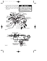
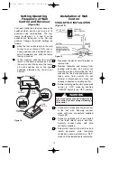


5. Connect one black wire of the wall
control to both remaining traveler wires
in the wall box and secure with wire
connector supplied.
NOTE: Retrofit 3-way installations are
likely to include two traveler wires
between the two wall boxes. In new
construction, only one traveler wire Is
required.
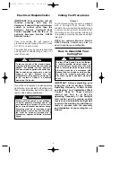
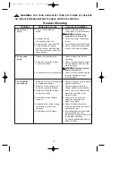
3-WAY WIRlNG DIAGRAM:
NEW CONSTRUCTION
6. Place wall control into wall box. Screw
in place and install decorator style
faceplate (included).
7. Next, install the other wall control into
the wall box containing the load wire.
Connect the black wire of the wall
control to the traveler wire(s) already
connected to the black wire (in the
other wall box). Secure with wire
connectors supplied.
8. Connect one black wire of the wall
control to the “load” (black) wire and
secure with wire connector supplied.
9.
Place the second wall control into the
wall box. Screw in place and install
decorator style faceplate (included).
Leave switch in “OFF” mode until fan
installation is completed.
10. Refer to page 5 and complete the
ceiling fan installation .
7. Refer to page 5 and complete the
ceiling fan installation.
Do not connect any neutral (white) wire to
this control. Incorrect wiring will damage
this control.
!
WARNING
EMERSON
®
HI
MED
LOW
FAN OFF
LIGHT
ON
OFF
BLACK
BLK
HOT
FAN/LIGHT
WALL
CONTROL
WALL
BOX
TO LOAD
TO
120VAC
SOURCE
G
RO
UN
D
Figure 20
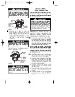
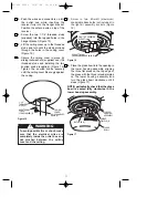
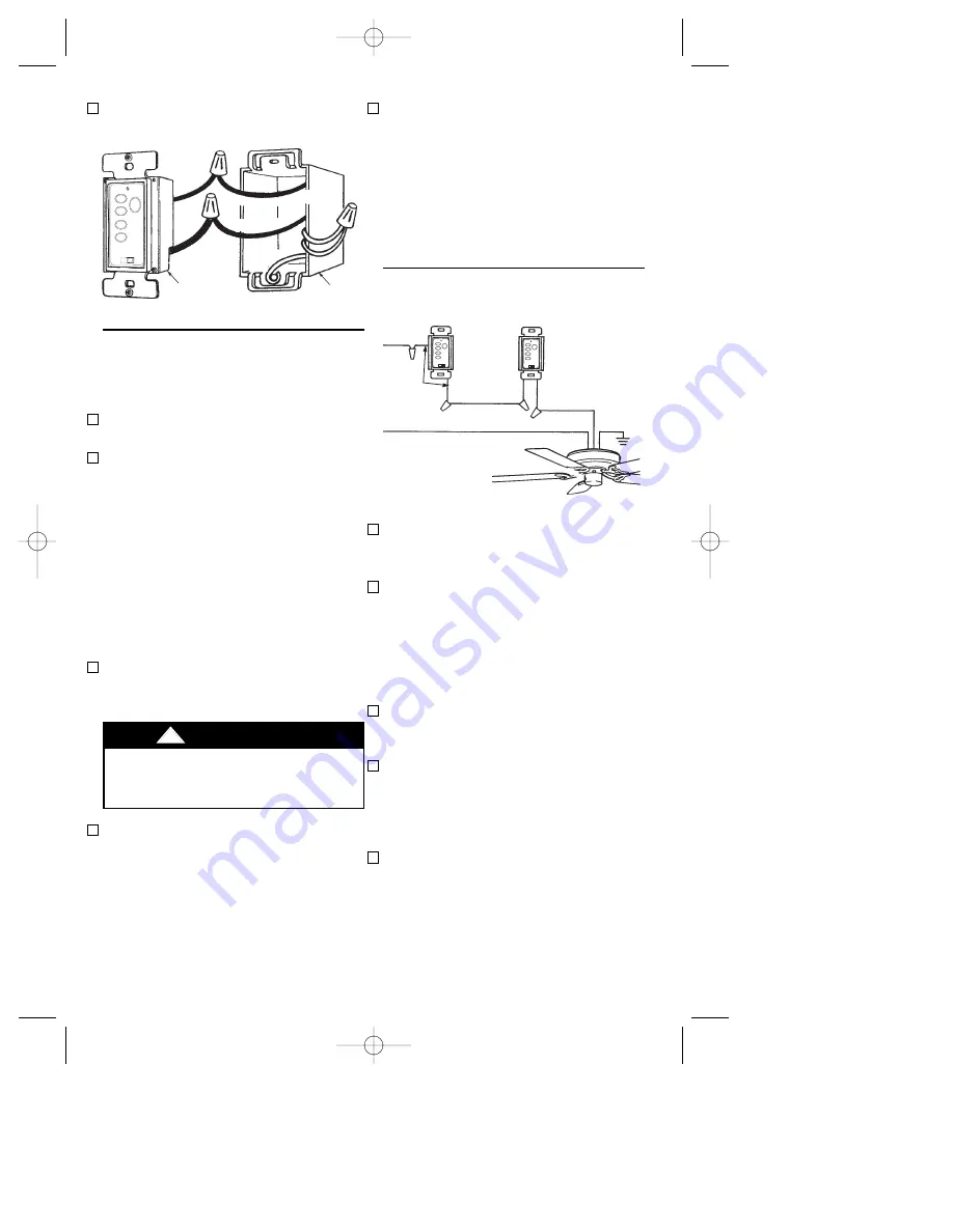
3-WAY INSTALLATION
(On fan controlled by two different wall
controls) (See Figures 21 and 22.)
1. Disconnect power at circuit breaker or
remove fuse.
2. At all wall box locations remove
faceplates and screws from existing
controls. Pull controls out from wall
boxes and determine which wall box
contains the “hot” lead and which wall
box contains the “load” wire. Also,
identify traveler wires which are
common to both wall boxes.
Disconnect wires from existing controls
only. Do not attempt to disconnect any
wires not already connected to existing
controls.
3. Before installing wall control, place wall
control in “OFF” mode by pushing
“ON/OFF” switch to the “OFF” position.
HOT
BLACK
FAN/LIGHT
WALL
CONTROL
TRAVELER
WIRE
BLK
BLK LOAD
BLACK
GROUND
NEUTRAL
REMOTE CONTROL
RECEIVER LOCATED
WITHIN THE CEILING
COVER
EMERSON
®
EMERSON
®
HI
MED
LOW
FAN OFF
LIGHT
ON
OFF
HI
MED
LOW
FAN OFF
LIGHT
ON
OFF
13
Figure 21
4. Install a wall control in the wall box
containing the “hot” wire first. Connect
the black wire of the wall control to the
“hot” wire. Securely connect wires with
wire connectors supplied.
BP7332 CF930 10/27/06 10:05 AM Page 13


