


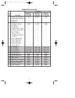
6
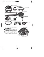
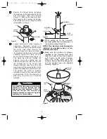
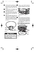
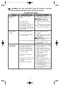
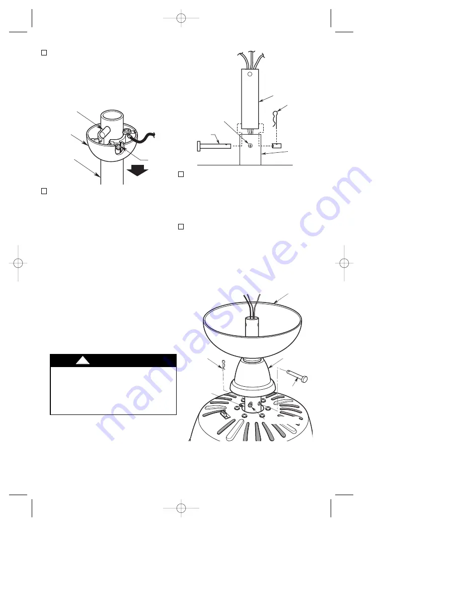
1. Remove the hanger ball by loosening
the setscrew in the hanger ball until the
ball falls freely down the downrod
(Figure 1). Remove the clevis pin from
the downrod, then remove the hanger
ball. Retain the pin and hanger ball for
reinstallation in step 5.
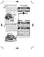
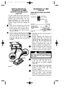
2. Loosen setscrew in motor coupling if
necessary. Separate, untwist and
unkink the three 80” motor leads. Route
the motor lead wires through the
downrod. Align the clevis pin holes in
the downrod with the holes in the motor
coupling. Install the clevis pin and
secure with the hairpin clip (Figure 2).
The clevis pin must go through the
holes in the motor coupling and the
holes in the downrod. Be sure to push
the straight leg of the hairpin clip
through the hole near the end of the
clevis pin until the curved portion of the
hairpin clip snaps around the clevis pin.
The hairpin clip must be properly
installed to prevent the clevis pin from
working loose. Pull on the downrod to
make sure the clevis pin is properly
installed.
PIN
HANGER
BALL
SETSCREW
DOWNROD
Figure 1
SETSCREW
CLEVIS PIN
MOTOR
COUPLING
DOWNROD
HAIRPIN
CLIP
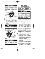
DOWNROD
HAIRPIN CLIP
MOTOR
COUPLING
SETSCREW (2)
CLEVIS PIN
Figure 2
HAIRPIN
CLIP
CLEVIS PIN
MOTOR
COUPLING
COUPLER
COVER
CEILING
CANOPY
SETSCREW (2)
Figure 3
It is critical that the clevis pin in the motor
coupling is properly installed and the
setscrew securely tightened. Failure to
verify that the pin and setscrew are
properly installed (as shown in Figure 2)
could result in the fan falling.
!
WARNING
3. While pulling up on the downrod,
securely tighten the two setscrews in
the motor coupling (Figure 3).
NOTE: The setscrews must be properly
installed as described above, or fan
wobble could result.
4. Make sure the grommet is properly
installed in the coupling cover then
slide the coupler cover on the downrod
until it rests on the motor housing.
Place the ceiling cover over the
downrod. Be sure both the ceiling cover
and the coupler cover are oriented
correctly (Figure 3).
BP7332 CF930 10/27/06 10:05 AM Page 6


