


7
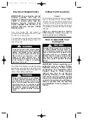
PARTIALLY
ASSEMBLED
FAN
SOLID
STYROFOAM
FACING OUT
6" - 8"
GAP
Figure 5
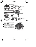
CEILING
COVER
PIN
DOWNROD
HANGER BALL
SETSCREW
Figure 4
SLIDE FAN BLADE
INTO CENTER SLOT
FAN BLADE
M5 x 12mm WASHER
HEAD BLADE SCREWS
(3 per blade)
CENTER SLOT
FAN
HOUSING
Figure 6
M4 x 10mm
SERRATED HEAD
SCREW (3)
LOWER
HOUSING
Figure 7
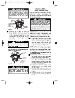
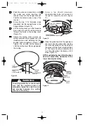
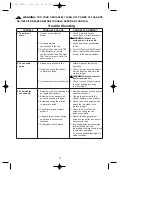
It is critical that the pin in the hanger ball
is properly installed and the setscrew
securely tightened. Failure to verify that
the pin and setscrew are properly
installed could result in the fan falling.
!
WARNING
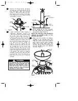
5. Reinstall the hanger ball (Figure 4) on the
downrod as follows. Route the motor
leads through the downrod. Position the
pin through the two holes in the downrod
and align the ball so the pin is captured in
the groove in the top of the hanger ball.
Pull the hanger ball up tight against the
pin and securely tighten the setscrew in
the hanger ball. A loose setscrew could
create fan wobble.
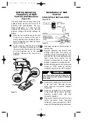
6. The fan comes with blue, black and
white leads that are 80” long. Before
installing fan, measure up approx-
imately 6 to 9-inches above top of
hanger ball/downrod assembly. Cut off
excess leads and strip back insulation
1/2-inch from end of leads.
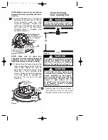
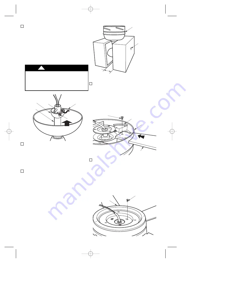
7. Turn fan motor assembly upside down
in preparation for mounting fan blades.
Position the top and bottom halves of
the styrofoam packaging on end, with
solid styrofoam facing outward. Set
side-by-side on the floor with a six to
eight-inch gap between the halves
(Figure 5). Carefully place the partially
assembled ceiling fan on the styrofoam
halves, with the hanger ball/downrod
assembly positioned in the gap and the
fan motor assembly resting on top of
the styrofoam ends.
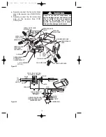
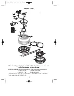
8. Slide blade through center slot in fan
housing. Mount blade to fan housing
using three M5 x 12mm washer head
blade screws (Figure 6).
9. Position the lower housing onto the fan
motor assembly, aligning each of the
the three holes. Attach the lower
housing to the fan motor assembly
using three M4 x 10mm serrated head
screws. Rotate the lower housing to
securely tighten by engaging the
screws in the two key hole slots
(Figure 7).
NOTE: Take care not to scratch fan
housing when installing blades.
BP7332 CF930 10/27/06 10:05 AM Page 7


