125
ADVANCED USER GUIDE
IP66/Nema 4X variable speed drive
MENU 16: PLC FUNCTIONS
CONTROL TECHNIQUES
3854 en - 03.2008 / b
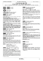
: Latch 1 ON source
: Latch 2 ON source
: Latch 3 ON source
: Latch 4 ON source
Adjustment range :
0.00
to
21.51
Factory setting
:
0.00
These parameters are used to select the enable source for
the latching relays. A pulse on an input causes the
corresponding output to change to 1.
Only "bit" type parameters can be assigned to these inputs. If
an unsuitable parameter is addressed on an input, the input
will be frozen at 0.
: Latch 1 OFF source
: Latch 2 OFF source
: Latch 3 OFF source
: Latch 4 OFF source
Adjustment range :
0.00
to
21.51
Factory setting
:
0.00
These parameters are used to select the disable source for
the latching relays. A pulse on an input causes the
corresponding output to change to 0.
Only "bit" type parameters can be assigned to these inputs. If
an unsuitable parameter is addressed on an input, the input
will be frozen at 0.
: Latch 1
OFF source inversion
: Latch 2
OFF source inversion
: Latch 3
OFF source inversion
: Latch 4
OFF source inversion
Adjustment range : 0 or 1
Factory setting
: 0
These parameters are used to invert the OFF source for the
latching relays.
0 (Disabled) (OFF): Source not inverted.
1 (Enabled) (On): Source inverted.
to
, :Not
used
to
,
to
,
and
to
: Latch 1 output destination
: Latch 2 output destination
: Latch 3 output destination
: Latch 4 output destination
Adjustment range :
0.00
to
21.51
Factory setting
:
0.00
These parameters are used to select the destination for the
latching relay outputs.
Only "bit" type parameters can be assigned to these outputs.
If an unsuitable parameter is addressed on an output, the
output will be frozen at 0.
: Current counter value
Adjustment range : 0 to 9999
Indicates the current counter value.
: Counter output state
Adjustment range : 0 or 1
0 (Disabled) (OFF): The current counter value is less than
the trip threshold.
1 (Enabled) (On):The current counter value has reached the
trip threshold.
: Upcounting counter input
Adjustment range : 0 or 1
0 (Disabled) (OFF)
1 (Enabled) (On)
A pulse on this input increments the counter value by 1.
Note:
• Slow pulse counting (<100 Hz):
Any function or digital input (except for DI4 and DI3) can be
assigned to
16.82
(upcounting) and
16.83
(downcounting).
• Fast pulse counting (<5 kHz):
Digital input DI4 (upcounting) assigned to
16.82
.
Digital input DI3 (downcounting) assigned to
16.83
.
Upcounting and downcounting fast pulses must not arrive
simultaneously.
: Downcounting counter input
Adjustment range : 0 or 1
0 (Disabled) (OFF)
1 (Enabled) (On)
A pulse on this input decrements the counter value by 1.
Note:
• Slow pulse counting (<100 Hz):
Any function or digital input (except for DI4 and DI3) can be
assigned to
16.82
(upcounting) and
16.83
(downcounting).
• Fast pulse counting (<5 kHz):
Digital input DI4 (upcounting) assigned to
16.82
.
Digital input DI3 (downcounting) assigned to
16.83
.
Upcounting and downcounting fast pulses must not arrive
simultaneously.
: Counter output trip threshold
Adjustment range : 0 to 9999
Factory setting
: 0
Used to determine the trip threshold which will cause the
counter output to change to 1.
: Initial counter value
Adjustment range : 0 to 9999
Factory setting
: 0
Used to determine a threshold value from which the counter
will upcount or downcount.
16.42
16.52
16.62
16.72
16.43
16.53
16.63
16.73
16.44
16.54
16.64
16.74
16.45
16.48
16.50
16.55
16.58
16.60
16.65
16.68
16.70
16.75
16.78
16.49
16.59
16.69
16.79
16.80
16.81
16.82
16.83
16.84
16.85

