72
ADVANCED USER GUIDE
IP66/Nema 4X variable speed drive
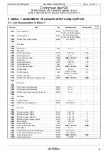
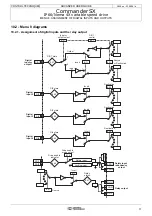
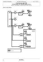
MENU 7: ASSIGNMENT OF ANALOG INPUTS AND OUTPUTS
CONTROL TECHNIQUES
3854 en - 03.2008 / b
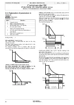
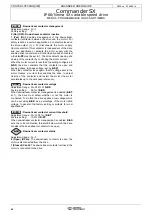
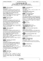
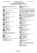
: ADI2 input destination
Adjustment range :
0.00
to
21.51
Factory setting
:
1.37
: Analog input 2 assigned to
analog reference 2
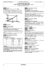
This address should contain the number of the parameter
which you wish to assign to input ADI2.
Only numerical parameters can be assigned if the input is
configured as an analog input and bit parameters if the input
is configured as a digital input.
If an unsuitable parameter is programmed, no assignment will
be taken into account.
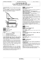
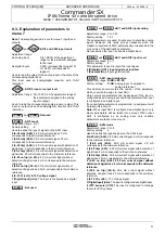
: ADIO3 mode
Adjustment range : 0 to 10
Factory setting
: 10
Used to define whether ADIO3 is used as an input or output
and the type of signal used.
0 (I:0-20mA) (0.20i): 0-20 mA current input, 0 mA corresponds
to the minimum reference.
1 (I:20-0mA) (20.0i): 20-0 mA current input, 20 mA corresponds
to the minimum reference.
2 (I:4-20mA trip) (4.20i): 4-20 mA current input with detection of
signal loss. 4 mA corresponds to the minimum reference.
3 (I:20-4mA trip) (20.4i): 20-4 mA current input with detection of
signal loss. 20 mA corresponds to the minimum reference.
4 (I:4-20mA no trip) (4.20i) : 4-20 mA current input without
detection of signal loss. 4 mA corresponds to the minimum
reference.
5 (I:20-4mA no trip) (20.4i) : 20-4 mA current input without
detection of signal loss. 20 mA corresponds to the minimum
reference.
6 (I:0-10V) (0.10i): 0-10 V voltage input.
7 (Digital input) (d-In): The input is configured as a digital input.
8 (O:0-20mA) (0.20o): 0-20 mA current output, where 20
mA corresponds to the maximum value of the assigned
parameter.
9 (O:4-20mA) (4.20o): 4-20 mA current output, where 20
mA corresponds to the maximum value of the assigned
parameter.
10 (Output 0-10V) (0.10o): 0-10 V voltage output, where
10 V corresponds to the maximum value of the assigned
parameter.
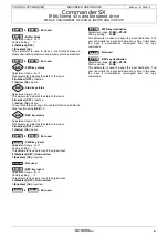
: ADIO3 scaling
Adjustment range : Input: 0 to 2.50
Output: 0 to 32.00
Factory setting
: 1.00
This parameter is used if necessary to scale the analog
output (or input). However, this rarely proves necessary since
the maximum value of the analog output (or input)
automatically corresponds to the maximum value of the
parameter which has been assigned.
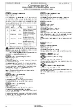
: ADIO3 input invert
Adjustment range : 0 or 1
Factory setting
: 0
Used to invert the input or output signal.
0 (Disabled) (OFF): Signal not inverted.
1 (Enabled) (On): Signal inverted.
: ADIO3 input destination/output source
Adjustment range :
0.00
to
21.51
Factory setting
:
5.04
This address should contain the number of the parameter
which you wish to assign to ADIO3.
Only numerical parameters can be addressed. If an
unsuitable parameter is programmed, the corresponding
output (or input) will take the value 0.
to
: Not used
to
: Current loop loss
ADI1 to ADIO3
Adjustment range : 0 or 1
In 4-20 mA current mode with detection of signal loss, this
parameter goes to 1 when the analog signal goes below 3
mA.
0 (Present) (On)
1 (Faulty) (OFF)
7.27
: corresponds to ADI1.
7.28
: corresponds to ADI2.
7.29
: corresponds to ADIO3. Detection does not work if
ADIO3 is used as an output.
to
: Not used
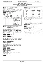
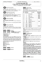
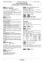
: ADIO3 feature
Adjustment range : 0 to 4
Factory setting
: 0
This parameter is used to assign the ADIO3 function quickly
when it is being used as an output.
7.33
causes
7.18
to be configured automatically in
accordance with the table below.
If ADIO3 is used as an input,
7.33
is forced to 4.
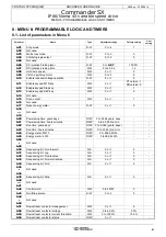
:IGBT junction temperature
Adjustment range : 0 to 200.0 °C
Indicates the measured temperature of the IGBT junction.
The drives trips when the temperature reaches 110 °C, and
can be reset when the temperature falls below 100 °C again.
to
: Not used
7.14
7.15
7.16
7.17
Value
LCD
display
LED
display
ADIO3 function
Value of
7.18
0
Motor spd.
SPd
Motor speed
5.04
1
Mot. load
Ld
Motor load
4.02
2
I mot.
A
Motor current
4.01
3
Output P
Puur
Output power
5.03
4
Any
Adv
Any assignment
0.00
7.18
7.19
7.26
7.27
7.29
7.30
7.32
7.33
7.34
7.35
7.57

