Controls, LEDs, and Connectors
COMX-CAR-610 COM Express Carrier Board Installation and Use (6806800K26D)
47
3.5.5
SPI Flash
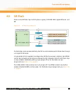
You must set the jumper defined below if you want to configure how the SPI flash is accessed.
Use Jumper P15 to enable or disable the BIOS on the COM Express module
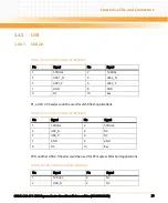
Table 3-34 P13, SPI Flash Header Pin Definition
Pin
Signal
1
3.3V DUAL
2
GND
3
SPI_CS_N
4
SF_SPI_CLK
5
SF_SPI_SO
6
SF_SPI_SI
7
NC
8
NC
Table 3-35 P12 and P14, Jumper Settings for SPI Flash SF100 header
P12 Jumper Setting
Configuration
P12 (1-2)
To PCH (Default)
P12 (2-3)
To SF100 header
P14 Jumper Setting
Configuration
P14 (1-2)
Enable SPI flash chip U9 and disable U10 (Default)
P14 (2-3)
Enable SPI flash chip U10 and disable U9
Table 3-36 P15 and P38, Jumper Configuration to Enable/Disable BIOS
P15 Jumper Setting
Configuration
P15 (1-2)
Enable BIOS on the module (Default)


