ControlWave GFC IS Communication Interface Manual (CI-CW-GFC-ISTRAN)
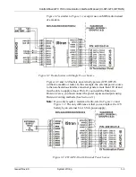
Figure 3-2
is similar to
Figure 3-1
except it uses an MDS radio instead
of a modem.
Figure 3-2. Radio System with Single Power Source
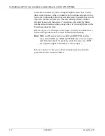
Figures 3-3
and
3-4
illustrate an externally powered CW-GFC-IS
(without a modem or radio). In this example, the external power source
to the non-hazardous interface must not generate more than 16Vdc and
must be able to supply at least 8Vdc. If you install the IStran in a
Division 2 area, you must connect the power inputs and outputs using
Division 2 wiring methods. (See
Section 4.1
.)
Note:
If you only require a modem or radio, refer to
Figure 3-1
and
Figure 3-2
. The only difference is that you can replace the 12V
battery by an external 8 to 16 Vdc power supply.
Figure 3-3. CW-GFC-IS with External Power Source
Issued Nov-09
System Wiring
3-3
Summary of Contents for ControlWave GFC IStran
Page 4: ...BLANK PAGE ...
Page 6: ...ControlWave GFC IStran Instruction Manual vi Contents Issued Nov 09 ...
Page 30: ...BLANK PAGE ...


