

AE21-1355 R4
October 2017
© 2017 Emerson Climate Technologies, Inc.
1
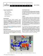
Digital Capacity Control for Copeland Discus
™
Refrigeration Compressors
TABLE OF CONTENTS
Safety Instructions ................................................................ 2
Safety Icon Explanation ................................................ 2
Safety Statements ........................................................ 3
Introduction ........................................................................... 4
Theory of Operation .............................................................. 4
Nomenclature ....................................................................... 5
Digital Performance .............................................................. 5
Operating Envelope .............................................................. 5
Control .................................................................................. 5
Control Requirements with Copeland
Controller .............................................................................. 7
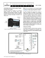
Compressor Wiring ............................................................... 7
Control Requirements with CoreSense Diagnostics ............. 8
Master Controller .................................................................. 8
Solenoid Valve/Gaskets ........................................................ 8
Thermistor ............................................................................. 8
Multiple Compressor Application ........................................... 9
General Guidelines and More Information .......................... 10
TABLE OF FIGURES
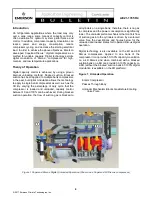
Figure 1 Copeland Discus Digital Unloaded Operation
(Shown on a Copeland 3D Discus) ....................................... 4
Figure 2 Copeland Discus Digital Loaded View (shown on a
Copeland 3D Discus) ............................................................ 5
Figure 3 Typical Modulated Power Reduction (for 3D Discus
Digital) .................................................................................. 6
Figure 4 Loaded vs Time ...................................................... 6
Figure 5 Copeland(R) Digital Compressor Controller ............. 7
Figure 6 Compressor Controller Wiring Diagram .................. 7
Revision Tracking R4
:
Pg. 4
– Note related to 6D Discus Digital availability
removed.
Pg. 5
– Note related to 6D Discus Digital availability
removed.
Pg. 8
– Title renamed to “Control Requirements with
CoreSense Diagnostics”
Pg. 8
– Reference to Intelligent Store Discus™ v2.x
changed to CoreSense Diagnostics
Pg. 8
– Reference to Intelligent Store Discus changed
to CoreSense Diagnostics
Pg. 8
– Link to E2 web page updated.
Pg. 9
– “Multiple Compressor Application” modified.
Pg. 10 - Reference to AE8-1351 changed to AE8-1368
"CoreSense™ Diagnostics v2.11 for Copeland
Discus™ Compressors"


