AGL_Stream_ST_4MTL_4MSL_E_Rev01
25
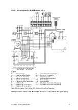
4.3.3.2
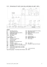
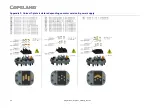
Wiring diagrams for Star/Delta motors (EW
…)
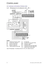
Legend
A4 ....... Sensor module
L1 ........ Current transducer CoreSense
A5 ....... Compressor terminal box
M21 ..... Fan motor / condenser
F6 ....... Fuse for control circuit
R2 ........ Crankcase heater
F7 ....... Fuse for control circuit
Y7 ........ Solenoid valve pumpdown
F8 ....... Fuse for control circuit
Y21 ...... Solenoid valve
F10 ..... Thermal protection switch M21
Y22 ...... Solenoid valve
K1 ....... Contactor M1
S1 ........ Thermistor chain motor temperature
K2 ....... Contactor M1 Y-connection
S2 ........ Thermistor chain motor temperature
K3 ....... Contactor M1
Δ-connection
Figure 30: Wiring diagram
– Direct-On-Line (EW…) motors with CoreSense Diagnostics
NOTE: The sensor module inside the terminal box requires a separate 24 VAC power supply.


