8
C6.1.11/0718-0619/E
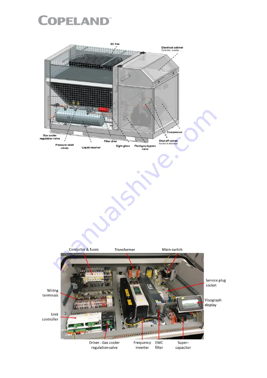
2.7 Main components description
Figure 7: Main components of CO
2
unit
2.7.1 Compressor
The compressor is installed in the chamber below the electrical cabinet. The standard delivery is with
shut-off valve on discharge, CoreSense Protection module, oil watch system connected to one of the
sight glass connections. One additional sight glass on the opposite side of the compressor allows for
a visual check of the oil level. A third sight glass located in the crankcase cover will give an indication
that there is oil on the inlet of the oil splasher.
All electrical wiring is pre-assembled in the factory. A pressure relief valve (135 bar) is installed
directly on the compressor. A pressure cut-out device is installed on the discharge side of the
compressor in compliance with EN 378 requirements.
2.7.2 Electrical cabinet
The electrical cabinet is located on the edge above the compressor chamber beside the fan. All
electrical components like main unit controller, inverter, contactors, transformers, wiring terminals
and fuses are installed in this area. The electrical cabinet is covered by a hinged upper shell which
can be fixed in two opening angles.
Figure 8: Electrical cabinet
Summary of Contents for Copeland EazyCool OME-4MTL-09X
Page 1: ...Copeland Eazycool CO2 Refrigeration Units Application Guidelines ...
Page 5: ......
Page 68: ...C6 1 11 0718 0619 E 63 ...


