AE4-1322
© 2002 Copeland Corporation
Issued 4-2002
Printed in U.S.A.
10
Pipe runs
Pipe runs
Pipe runs
Pipe runs
Pipe runs
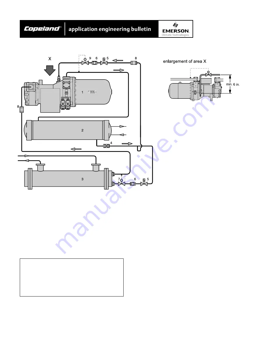
To ensure a bubble free liquid supply to the liquid
injection valve, the connection must be made on the
bottom of a horizontal section of the liquid line.
Installation of the liquid inject valve at the com-
Installation of the liquid inject valve at the com-
Installation of the liquid inject valve at the com-
Installation of the liquid inject valve at the com-
Installation of the liquid inject valve at the com-
pressor
pressor
pressor
pressor
pressor
•
Min. 6 to 8 in. above liquid injection connection
CAUTION!
CAUTION!
CAUTION!
CAUTION!
CAUTION!
V
V
V
V
Vibration fractures possible! install liquid
ibration fractures possible! install liquid
ibration fractures possible! install liquid
ibration fractures possible! install liquid
ibration fractures possible! install liquid
injection and solenoid valves with
injection and solenoid valves with
injection and solenoid valves with
injection and solenoid valves with
injection and solenoid valves with
adequate supports!
adequate supports!
adequate supports!
adequate supports!
adequate supports!
Check for vibration during operation!
Check for vibration during operation!
Check for vibration during operation!
Check for vibration during operation!
Check for vibration during operation!
Calculating the cooling capacity of the liquid
Calculating the cooling capacity of the liquid
Calculating the cooling capacity of the liquid
Calculating the cooling capacity of the liquid
Calculating the cooling capacity of the liquid
injection valve
injection valve
injection valve
injection valve
injection valve
•
With the selection software
•
Consider the most extreme conditions to be
expected during actual operation:
- min. evaporating temperature
- max. suction gas superheat and condensing
temperature
Further conditions for valve selection
Further conditions for valve selection
Further conditions for valve selection
Further conditions for valve selection
Further conditions for valve selection
•
Pressure at the injection point:
- R134a approximately 30 to 45 psig above
suction pressure R407C, R22 approx. 40 to
50 psig above suction pressure
- Never size the valve too large danger of
refrigerant flooding!
Additional components in the liquid line
Additional components in the liquid line
Additional components in the liquid line
Additional components in the liquid line
Additional components in the liquid line
•
Solenoid valve (energized parallel to compressor
contactor)
•
Filter dryer (if required)
•
Liquid sight glass
Figure 7
Liquid injection valve (system design)


