14
C6.1.7/1110-0519/E
3.4.3 Discharge temperature protection
Under extreme operating conditions internal discharge temperatures can reach very high levels.
The HLR Receiver units are equipped with digital gas temperature control on the compressor top
cap, connected directly to the EC2-552 controller.
3.4.4 Electrical protection standard (protection class)
▪
Compressors: IP21 according to IEC 34.
▪
HP-LP and LP safety pressure switches (Alco PS2 and PS1): IP44 according to EN 60529/IEC
529.
▪
HP safety pressure switch PS3 with cable assy: IP65 according to EN 175301-803/IEC 529.
▪
EC2-552 controller: IP65 (frontal protection with gasket).
3.4.5 HLR Receiver unit electrical data
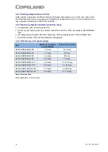
Unit
Maximum operating
current (MOC)t
Locked rotor current
HLR13-ZBD30KCE-TFD
7.5 Amp
51.5 Amp
HLR13-ZBD45KCE-TFD
11.4 Amp
74 Amp
HLR13-ZBD58KCE-TFD
16.4 Amp
95 Amp
HLR13-ZBD76KCE-TFD
20.4 Amp
118 Amp
HLR31-ZBDT60KCE-TFD
18.2 Amp
2 x 51.5 Amp
HLR31-ZBDT90KCE-TFD
24.5 Amp
2 x 74 Amp
HLR31-ZBDT116KCE-TFD
31.8 Amp
2 x 95 Amp
HLR31-ZBDT152KCE-TFD
40.8 Amp
2 x 118 Amp
Table 9: Electrical data
TFD: 380-420 V / 3 Ph / 50 Hz


