background image


C6.1.7/1110-0519/E 


15 

Starting up & operation 

Before  commissioning,  ensure  that  all  Rotalock  valves  and  other  valves  on  the  unit  are  fully 
opened. 

4.1  Charging procedure 

4.1.1  Refrigerant charging procedure 

It  is  recommended  to  charge  the  unit  with  refrigerant  into  the  receiver,  via  the  Rotalock  service 
valve. 

Alternatively,  it  could  also  be  done  by  charging 

gas

  through  the  suction  valve  of  the  compressor. 

The charging procedure should follow the rules of art of refrigeration. 

Recommendation is to break vacuum in the system with partial charge of refrigerant, then start the 
system. 

For charge adjustment it is recommended to check the liquid sight glass just before the expansion 
valve. 

4.1.2  Oil charging procedure 

HLR  Digital  Receiver  units  are  supplied  only  with  a  compressor  oil  charge.  After  commissioning, 
the oil level should be checked and topped up if necessary. 

NOTE: The oil level should be approximately halfway up the sight glass. 

Emerson recommends charging the unit with one of the following oil types: 

  Emkarate RL 32 3MAF 

  Mobil EAL Artic 22 CC 

Charging is done through the Schräder valve located on the suction Rotalock valve. 

Two-compressor Digital Receiver units equipped with an oil separator are delivered with a small oil 
can to add oil, if necessary. 

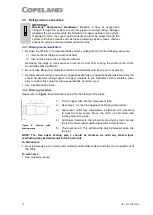
4.2  Rotation direction of scroll compressors 

Scroll  compressors,  like  several  other  types  of  compressors,  will  only  compress  in  one  rotational 
direction.  The  rotation  direction  is  not  an  issue  with  single-phase  compressors  since  they  will 
always start and run in the proper direction. Three-phase compressors will rotate in either direction 
depending upon the power phasing. Since there is a 50-50 chance of connecting power in such a 
way  as  to  cause  rotation  in  the  reverse  direction, 

it  is  important  to  include  notices  and 

instructions  in  appropriate  locations  on  the  equipment  to  ensure  proper  rotation  direction 
when the system is installed and operated.


Observing  that  suction  pressure  drops  and  discharge  pressure  rises  when  the  compressor  is 
energized allows verification of proper rotation direction. There is no negative impact on durability 
caused by operating three-phase Scroll compressors in the reversed direction for a short period of 
time  (under  one  hour)  but  oil  may  be  lost.  After  several  minutes  of  operation  in  reverse,  the 
compressor's  protection  system  will  trip  due  to  high  motor  temperature.  However,  if  allowed  to 
repeatedly  restart  and  run  in  reverse  without  correcting  the  situation,  the  compressor  will  be 
permanently damaged. 

All  three-phase  Scroll  compressors  are  identically  wired  internally.  Therefore,  once  the  correct 
phasing is determined for a specific system or installation, connecting properly phased power leads 
to the identified compressor terminals in the electrical panel will ensure proper rotation direction. 

4.3  Maximum compressor cycle 

Maximum permitted starts per hour: 10. 

It can be controlled via the EC2-552 controller (parameter t3, t4 and/or t5). 


Summary of Contents for Copeland Scroll Digital HLR Series

Page 1: ...Copeland Scroll Digital Receiver Units HLR Application Guidelines ...

Page 2: ... Pressure switch 5 2 7 5 Liquid line equipment 6 2 7 6 Solenoid valve for Copeland Scroll Digital compressor 7 2 7 7 Oil separator Alco Controls OSH 7 2 8 Electronic controller EC2 552 7 2 8 1 Select parameter configuration 7 2 8 2 Parameter modification 8 2 8 3 Main parameters on EC2 552 8 3 Installation 10 3 1 Receiver unit handling 10 3 1 1 Transport and storage 10 3 1 2 Weights 10 3 2 Connecti...

Page 3: ...peration 15 4 1 Charging procedure 15 4 1 1 Refrigerant charging procedure 15 4 1 2 Oil charging procedure 15 4 2 Rotation direction of scroll compressors 15 4 3 Maximum compressor cycle 15 4 4 Checks before starting up and during operation 16 5 Maintenance repair 16 6 Certification approval 16 7 Dismantling disposal 16 DISCLAIMER 16 ...

Page 4: ...anufacturer s Declaration and other declarations available at www climate emerson com en gb These instructions should be retained throughout the lifetime of both the compressor and the unit You are strongly advised to follow these safety instructions 1 1 Icon explanation WARNING This icon indicates instructions to avoid personal injury and material damage CAUTION This icon indicates instructions t...

Page 5: ...r protective equipment gloves eye protection etc must be used at all times POE must not come into contact with any surface or material that it might damage including without limitation certain polymers eg PVC CPVC and polycarbonate IMPORTANT Transit damage Compressor and or unit malfunction Use original packaging Avoid collisions and tilting The contractor is responsible for the installation of th...

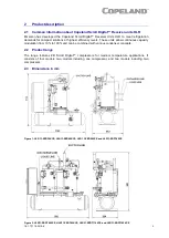
Page 6: ...ow continuous capacity modulation from 10 to 100 and can be combined with various condenser concepts 2 2 Product range The range features ZB Scroll Digital compressors for medium temperature applications It consists of four models two models including one compressor and two models including two compressors 2 3 Dimensions in mm Figure 1 HLR 13 ZBD30KCE HLR13 ZBD45KCE HLR 13 ZBD58KCE and HLR13 ZBD76...

Page 7: ...l compressors brochures or Copeland brand products Select software available at www climate emerson com en gb Qualified refrigerants R404A R407A R407F R448A R449A R450A R513A R134a Qualified oil Emkarate RL 32 3MAF Qualified servicing oils Emkarate RL 32 3MAF MOBIL EAL Arctic 22 CC Table 1 Qualified refrigerants and oils 2 6 2 Application limits For application envelopes please refer to Select sof...

Page 8: ...arge the system with refrigerant via the Rotalock service valves 2 7 3 Electrical box components All electrical components are pre wired into the panel The panel contains compressor contactor s fuse s terminal blocks DIN rail mounted terminals alarm relays electronic controller NOTE For further information please refer to Application Guidelines C6 1 3 Condensing Unit Controller for Copeland EazyCo...

Page 9: ...ch point settings Cut out point 26 2 bar Cut in point 22 bar 4 Alco Controls PT5 Pressure Transmitter Digital Receiver units are equipped with HP and LP pressure transmitters connected to the EC2 552 electronic unit controller see chapter 2 8 Electronic controller EC2 552 An Alco PT5 30M pressure transmitter is used at the high pressure part of the system An Alco PT5 07M pressure controller is use...

Page 10: ...r staging based on suction pressure TCP IP Ethernet connection with web server functionality to allow monitoring and configuration of controllers through a standard web browser alarm messaging by email fan speed control if an Alco Controls FSP150 fan speed controller is installed Figure 3 Electronic controller EC2 552 The controller has been pre programmed with a number of parameter values that ar...

Page 11: ...temporarily confirm the new value and display its code Repeat the procedure from step 1 press or to show to modify other parameters To exit and confirm parameters with the new values Press PRG to confirm the new values and exit the parameter modification procedure To exit without modifying any parameter Do not press any button for at least 60 seconds TIME OUT 2 8 3 Main parameters on EC2 552 The E...

Page 12: ...mum output values can be adjusted In case of a single compressor unit with a Digital Scroll compressor the maximum output could be set below 100 if the system requests less than the maximum capacity In that case F3 F2 NOTE For further information please refer to Application Guidelines C6 1 3 Condensing Unit Controller for Copeland EazyCool Outdoor Condensing Units available on www climate emerson ...

Page 13: ...al or handling equipment according to weight Keep in the upright position Respect stacking loads according to Figure 4 Do not stack anything on top of the unit packaging Keep the packaging dry at all times Respect the maximum number of identical packages which may be stacked on one another where n is the limiting number Transport n 3 Storage n 3 Figure 4 Maximum stacking loads for transport and st...

Page 14: ...BD45KCE HLR 13 ZBD58KCE and HLR13 ZBD76KCE Figure 6 HLR31 ZBDT60KCE HLR31 ZBDT90KCE HLR31 ZBDT116KCE and HLR31 ZBDT152KCE 3 2 2 Access door to electrical box Use supplied key to open and close the electrical box door Figure 7 Discharge line Liquid line Suction line Suction line Discharge line Liquid line Suction line ...

Page 15: ... a copper phosphorous or copper phosphorous silver alloy rod should be used for joining copper to copper whereas to join dissimilar or ferric metals a silver alloy rod either flux coated or with a separate flux would be used Use a double tipped torch 3 3 2 Brazing procedure Please refer to Figure 8 and procedure below for the brazing of the tubes 1 Fit the copper tube into the compressor tube 2 He...

Page 16: ...2 2 Electronic controller EC2 552 EC2 552 EC2 552 EC2 552 Crankcase heater 1 1 1 1 HP LP Pressure switch PS2 1 1 1 1 HP Pressure switch PS3 LP Pressure switch PS1 Digital 24V solenoid valve 1 1 1 1 Table 7 Electrical connections Single compressor units Pre wired electrical components Tandem compressor units HLR13 ZBDT60KCE HLR13 ZBDT90KCE HLR31 ZBDT116KCE HLR31 ZBDT152KCE Compressor contactor 2 x ...

Page 17: ... and PS1 IP44 according to EN 60529 IEC 529 HP safety pressure switch PS3 with cable assy IP65 according to EN 175301 803 IEC 529 EC2 552 controller IP65 frontal protection with gasket 3 4 5 HLR Receiver unit electrical data Unit Maximum operating current MOC t Locked rotor current HLR13 ZBD30KCE TFD 7 5 Amp 51 5 Amp HLR13 ZBD45KCE TFD 11 4 Amp 74 Amp HLR13 ZBD58KCE TFD 16 4 Amp 95 Amp HLR13 ZBD76...

Page 18: ...ill only compress in one rotational direction The rotation direction is not an issue with single phase compressors since they will always start and run in the proper direction Three phase compressors will rotate in either direction depending upon the power phasing Since there is a 50 50 chance of connecting power in such a way as to cause rotation in the reverse direction it is important to includ...

Page 19: ... Art 3 3 Sound Engineering Practice The units and their components as far as required are CE marked and thereby establish conformity with the relevant directives Conformity Declarations for components are available as far as required The Manufacturer s Declaration of Incorporation has to be respected when incorporating these products into a machine 7 Dismantling disposal Removing oil and refrigera...

Page 20: ...outh Dubai UAE Tel 971 4 811 81 00 Fax 971 4 886 54 65 mea sales emerson com ASIA PACIFIC Suite 2503 8 25 F Exchange Tower 33 Wang Chiu Road Kowloon Bay Kowloon Hong Kong Tel 852 2866 3108 Fax 852 2520 6227 CZECH REPUBLIC Hajkova 22 CZ 133 00 Prague Tel 420 733 161 651 Fax 420 271 035 655 Pavel Sudek emerson com SPAIN PORTUGAL C Pujades 51 55 Box 53 ES 08005 Barcelona Tel 34 93 412 37 52 iberica s...

Reviews: