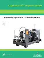
background image

Copeland Scroll

®

 Compressor Module

Installation, Operation & Maintenance Manual

Model Family 
SZO22
SZV22

Summary of Contents for Copeland Scroll SZO22

Page 1: ...Copeland Scroll Compressor Module Installation Operation Maintenance Manual Model Family SZO22 SZV22 ...

Page 2: ......

Page 3: ...ures 5 2 3 Ambient Temperature Range 6 2 4 Installation Clearance and Dimensions 7 2 5 Process and Instrumentation Diagrams P IDs 8 2 6 Electrical Controls 9 2 6 1 General Considerations 9 2 6 2 Oil Cooler Fan Control 10 2 6 3 Compressor Module Motor Protection 12 2 6 4 Electrical Requirements 13 2 6 5 Wiring 14 2 6 6 Variable Frequency Drive VFD Terminations 15 3 0 Operation 15 3 1 Initial Startu...

Page 4: ...otor Winding Resistance 22 5 3 Platform Symptoms Diagnosis 23 6 0 Specifications 24 7 0 Technical Support and Service 25 Appendix A Material Data Safety Sheet 26 A 1 Supplier 26 A 2 Product Name and Information 26 A 3 Components and Hazard Statement 26 A 4 Safe Handling and Storage 26 A 5 Physical Data 26 A 6 Fire and Explosion Hazards 27 A 7 Reactivity Data 27 A 8 Health Hazard Data 27 A 9 Person...

Page 5: ...High Temperature Fan Control System 11 Figure 9 Oil Cooling and Thermal Valve 11 Figure 10 Motor Control 12 Figure 11 Typical Compressor Module Electrical Requirements 13 Figure 12 Control Circuit Terminations 14 Figure 13 Maintenance Tools 18 Figure 14 Gas Inlet Block and Screen 21 Figure 15 Scavenge Line Orifice 21 TABLES Table 1 Inlet and discharge pressure limits 5 Table 2 Typical Compressor M...

Page 6: ...V22C1A EDE 140 190 100 15 215 2 W C 5 mbarg 280 138 250 NO 356 NOTE SZO modules are intended for use with clean dry gas in applications with moderate ambient temperatures Oil thermal bypass valve setpoint is 200 F Most SZO module applications use PAO oil SZV modules keep discharge gas temperatures elevated to help with dewpoint control SZV modules insulate the separators and use a 250 F oil therma...

Page 7: ...azard warnings before performing any work on the Compressor Module Maintain all Compressor Module operation and hazard warning labels WARNING Flammable gas can form explosive mixtures with air Explosive gases can cause property damage serious personal injury or death WARNING Failure to disconnect and lockout electrical power from the Compressor Module before attempting maintenance can cause shock ...

Page 8: ...following words and be aware of the potential for personal injury or property damage WARNING A Warning describes hazards that CAN or WILL cause serious personal injury death or major property damage CAUTION A Caution describes hazards that CAN cause personal injury or property damage NOTE A Note indicates special instructions that are very important and must be followed 2 Form No 2008SSD 34 5 11 ...

Page 9: ...es an overview of these components These terms are used throughout this manual Compressor Module the SZO22 Compressor Module shown in Section 1 1 Compressor a Copeland Scroll Compressor Compressor Package the entire assembly including the Compressor Module ready for service in the field Packagers the company that prepares the Compressor Module for service VFD Variable Frequency Drive used to power...

Page 10: ...sor Package The Compressor Package consists of the Compressor Module housed in an assembly ready for service in the field Equipment Packagers customize the assembly and complete the fabrication for Compressor Modules for each application Figure 3 shows a simplified example of a Compressor Package Figure 3 Typical Compressor Package Oil cooler Gas aftercooler if applicable Control and power panel C...

Page 11: ...lid debris also must be removed from the gas prior to compression When required use a 5 to 10 micron inlet filter to remove debris from the gas stream The degree of filtration required depends on the specific application 2 2 Inlet and Discharge Pressures Refer to Table 1 for acceptable inlet and discharge pressure levels Table 1 Inlet and discharge pressure limits Type Level Operating Guidelines M...

Page 12: ...s bypass recycle valve was removed from some of the scroll modules Packagers will need to install pressure relief downstream of our module See table on page iv 2 3 Ambient Temperature Range The Compressor Module operating ambient temperature is 20 F to 122 F 29 to 50 C For details on ambient temperatures for VFD startup and Compressor Module operation see Table 10 on page 24 ...

Page 13: ...for gas and electrical connections at the rear of the Compressor Module Check applicable national and local electrical codes Cooling air flow is back to front from the gas connection end to the oil cooler end Do not block or restrict the cooler fans or oil cooler Refer to Figure 4 for the dimensions of the Compressor Module Figure 4 Compressor Module Dimensions in mm ...

Page 14: ...Module Installation 2 5 Process and Instrumentation Diagrams P IDs Figure 5 Compressor Module Gas and Oil Flow Diagram and Safety Shutdowns Single Compressor Module Gas Oil Flow Diagram Safety Shutdowns Gas bypass valve shown is optional ...

Page 15: ...osed opens on pressure rise High Temperature Normally Closed opens on temperature rise Electrical Considerations Variable Speed Compressor Module Compressor power for a variable speed Compressor Module is the Variable Frequency Drive VFD Compressor speed control can be either a 4 20 mA or 0 10V signal transducer supplied by customer applied to the VFD Speed can also be manually controlled with a p...

Page 16: ...C control signal that is applied to the yellow lead on the fan terminal strip Standard Compressor Modules use a nonlinear PTC thermistor to monitor oil temperature and provide a speed signal High temperature Compressor Modules use a linear NTC thermistor to monitor oil temperature This signal is available to support a customer provided fan speed control circuit All power connections are wired to t...

Page 17: ...755 LPM flow rate Thermal oil bypass valve standard setting 200 F 93 C 250 F model specific Thermal bypass valve operation valve s purpose is to provide discharge temperature control Oil flow on valve is A to B when the unit is cold and A to C when the heat rises see Figure 9 Figure 9 Oil Cooling and Thermal Valve A B C Oil Cooler Return to Compressor 1st Stage Separator ...

Page 18: ... 3 Compressor Module Motor Protection Variable Speed Compressor Module Protection The VFD provides overload protection for the compressor Module capacity can be changed by varying the typical Compressor speed ranging from 2400 to 4800 rpm Figure 10 Motor Control ...

Page 19: ...quency 50 60 Hz Low Voltage DC Specifications Oil Cooler Fan Voltage and Power Fan motor voltage 24VDC Total fan motor current 4 5A Additional power may be required to support customer logic and control circuits Contact factory for information about single phase applications Reduced capacity at 50 Hz Code Description 1 Control Techniques VFD 10 or 15 HP model specific 2 24VDC power supply 3 PLC or...

Page 20: ...14 2008SSD 34 5 11 Single Compressor Module Installation 2 6 5 Wiring Figure 12 Control Circuit Terminations Control Wiring Terminations ...

Page 21: ...r systems with power lead lengths in excess of 200 ft 61m between the VFD and Compressor Module terminal box LOW VOLTAGE DEVICES Verify these conditions for low voltage devices ___ 1 DC polarity is correct ___ 2 Temperature control device if other than standard thermistor control is working properly SAFETY AND CONTROL DEVICES Make sure that all safety and control switches and devices are configure...

Page 22: ...r Packager s user manual for information on procedures to start up the Compressor Package which includes equipment added to the Compressor Module by the Packager 3 3 Normal Operation Checklist Observe the following conditions after startup when power is applied to the VFD and the VFD receives the signal from the Compressor Package control system to run CHECK FOR THESE CONDITIONS UNDER NORMAL OPERA...

Page 23: ...quent service 4 3 Oil Service page 19 Check the condition of the lubricant periodically Normal color is clear or light gray Change the oil filter if equipped annually or as required Gas Inlet System Inspect and clean the inlet screen annually or more often as needed A restricted inlet screen will result in reduced flow 4 6 Cleaning the Inlet Screen page 21 Second Stage Separator System Inspect and...

Page 24: ...7ml of oil Move the pump handle slowly using long slow full strokes Note The hose fittings contain a core depressor that opens the Schrader valve when the fittings are attached A backseating control valve can be used to open the Schrader valves on the Compressor Module When the knob is turned fully counterclockwise the core depressor is retracted and the backseating control valve can be installed ...

Page 25: ...yover 1 System is overfilled with oil The oil level should never reach the top of the primary oil separator top site glass under any operating condition 2 No back pressure on the discharge when the compressor is turned off resulting in oil foaming and carrying over to the secondary oil separator Check upper site glass when the compressor is first turned off 3 Contaminated or oil saturated secondar...

Page 26: ... line orifice or screen is restricted Clean or replace Insufficient back pressure Confirm 50 60 psig or higher backpressure when the compressor is running No specific cause found Replace oil separator block assembly scavenge line and secondary oil separator element ...

Page 27: ...ervice 9 Check for leaks at all fittings that have been disturbed 4 5 Servicing the Scavenge Line Orifice The scavenge line orifice in the oil separator block must remain clear of obstruction If this orifice is restricted the secondstage oil separator can become saturated increasing oil consumption Note image shown is 90 degree orifice Procedure is the same for straight orifice Figure 15 Scavenge ...

Page 28: ...tips for troubleshooting 5 1 Troubleshooting Guide Refer to Table 6 for recommended solutions to typical problems Table 4 Troubleshooting Problem Recommended Actions Low Inlet Gas Pressure Fault Closed gas inlet valve Restricted or insufficient gas supply Blocked inlet filter screen located internally on the Compressor Module inlet block High Oil Temperature Fault Blocked air flow across oil coole...

Page 29: ...d or dirty secondstage oil separator High oil level Restricted scavenge orifice Insufficient back pressure Oil dilution Compressors Won t Run Determine drive status Is inhibit circuit closed Is run signal present Does the VFD indicate a fault code Incorrect Compressor Speed Low inlet pressure High discharge pressure High temperature fan low oil oil cooler Problem with speed control sensor and rela...

Page 30: ...luid ounces 5 0 liters Projected oil consumption 2 Approximately 40 oz 0 9 l 8 000 hours at 0 25 psig suction 5 ppm System Electrical Standard Minimum VFD ambient startup temperature3 4 14 F 10 C Power supply to inverter Voltage range Input frequency range 380 to 480VAC 50 60 Hz Overpressure detection outlet 215 psig open Underpressure detection inlet 0 75 psig open low pressure system 2 water col...

Page 31: ...d MI 48642 Emergency Number 989 496 3780 A 2 Product Name and Information Product Trade name and synonyms CP 6006 Series Chemical Name Poly Alpha Olefin PAO Chemical Family Synthetic Hydrocarbon Formula C10n H20n 2 CAS Proprietary A 3 Components and Hazard Statement This product is non hazardous The product contains no known carcinogens No special warning labels are required under OSHA 29 CFR 1910...

Page 32: ...ire and Explosion Hazards A 8 Health Hazard Data Threshold Limit Value 5mg m3 ACGIH Situations to Avoid Avoid breathing oil mists First Aid Procedures Ingestion Consult physician at once DO NOT INDUCE VOMITING May cause nausea and diarrhea Inhalation Product is not toxic by inhalation If oil mist is inhaled remove to fresh air and consult physician To the best of our knowledge the toxicity of this...

Page 33: ......

Page 34: ... Cudahy WI 53110 8904 P 414 744 0111 F 414744 1769 www vilter com Copeland Scroll and Emerson are trademarks of Emerson Electric Co or one of its affiliated companies 2011 Emerson Climate Technoligies Inc All rights reserved Printed in the USA 2008SSD 34 R2 ...

Reviews: