6
C6.2.38/0719/E
The oil tests on sample compressors with an external oil sight tube must be carried out by the system
designer in the lab. This will allow to investigate the oil return behaviour to the compressor. In case
some oil remains in the system, eg, in the tubes, heat exchangers or other components, oil top-up is
required. A sufficient oil level must be present in the compressor at all times to ensure proper
compressor reliability.
2.6.4 Test procedure
▪
Before first compressor start, mark the 116-mm maximum oil level, the 75-mm minimum level and
the 50-mm extreme minimum level. The distance to the markings can be measured from the lower
end of the compressor housing
– see
Figure 2
.
▪
Start the compressor with a nominal speed of 3500 revolution per minute and run the system until
it reaches stable conditions, then run at stable conditions for a minimum of 15 minutes. Any oil
level between 116 mm and 75 mm is in the nominal range and is acceptable.
▪
Always check the level in the external oil sight tube. The oil level between 116 and 75 mm is the
target. During the measurements and for short and transient periods, an oil level between 75 and
50 mm can be tolerated. Once the level falls below the 50-mm marking, stop the compressor
immediately. Any oil level below the 50-ml marking is not acceptable.
▪
Top-up some oil if necessary and record the amount of topped-up oil. This could be the reference
for all future systems with the same design. Perform the test anew to check the oil return
behaviour again, as described above.
▪
If the oil level rises above the maximum level, compressor performance could start to drop due to
the extra amount of oil. This situation will not harm the compressor, but it is recommended to
remove the extra oil quantity in order to reach the nominal range.
▪
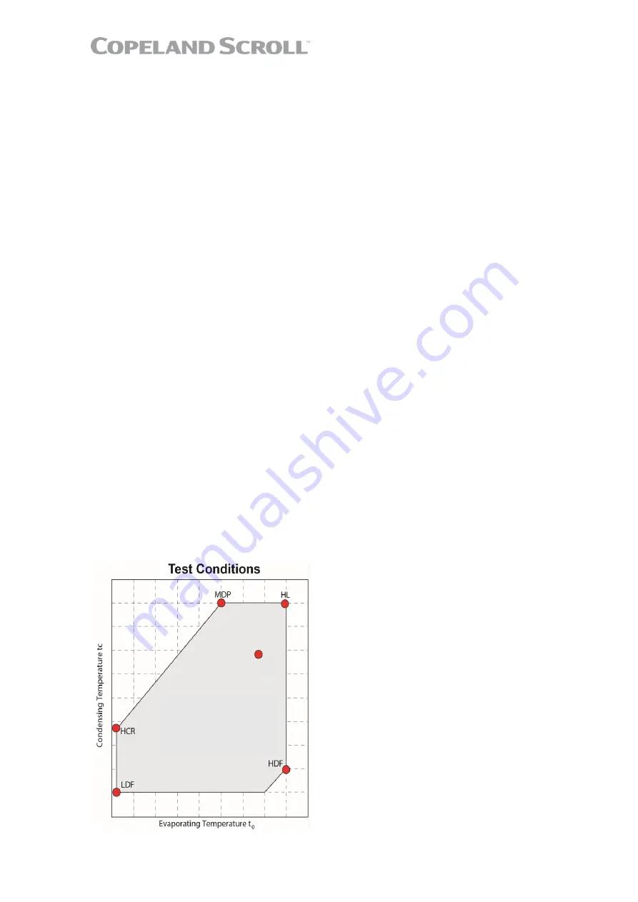
Repeat the test at different operating conditions, starting with the main operating point. Test
different operating points in the corners of the operating envelope as well. Refer to
Figure 4
for
main operating point, high load HL, maximum differential pressure MDP, high compression ratio
HCR, low density flow LDF, high density flow HDF.
▪
Also perform tests for different system operations, eg, part load, defrost, bypass etc. Make sure
the tests cover all possible different system conditions.
▪
The influence of the variable speed operation must also be observed. Perform additional tests
with low speed at the MDP/HCR corner and with low speed + high speed at the HL point.
▪
Record the bottom shell temperature under all tested conditions. The bottom shell temperature
together with the evaporating temperature give an indication whether liquid refrigerant is returning
or diluted in the compressor oil sump. The compressor sump temperature must remain above the
evaporating temperature as shown in
Figure 5
. Otherwise adjustments need to be done in the
design, refrigerant charge or superheat setting of the expansion device in order to always operate
in the safe area.
Figure 4: Testing points for oil return behaviour investigation
Summary of Contents for Copeland Scroll YBVH021 1U-3E9
Page 5: ......


