11
© 2014 Emerson Climate Technologies, Inc.
Printed in the U.S.A.
AE4-1317 R10
Application Engineering
B
U
L
L
E
T
I
N
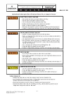
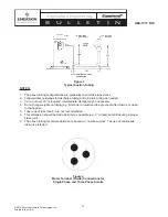
NOTES:
1. The above tubing con
fi
gurations are guidelines to minimize tube stress.
2. Follow similar guidelines for discharge tubing and oil return tubing as needed.
3. If a run of over 20” is required, intermediate clamps may be necessary.
4. Do not hang weights on tubing (e.g.
fi
lter drier on suction tubing) except after clamps or close
to the header.
5. Tube runs of less than 8” are not recommended.
6. This dimension should be made as short as possible (e.g. 2” or less) but still insuring a proper
braze joint.
7. The above tubing recommendations are based on “no elbow joints”. The use of continuous
tubing is preferred.
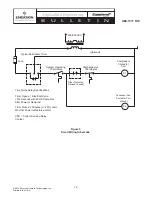
Figure 4
Motor Terminal (Fusite) Connections for
Single Phase and Three Phase Scrolls
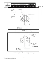
Figure 3
Typical Suction Tubing


