17 Electrical
Installation
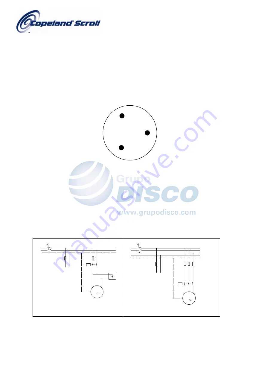
Independently from the internal motor protection, fuses F6...8 have to be installed before the compressor as shown in
Figure 8 and Figure 9. Selection of fuses has to be carried out according to VDE 0635 or DIN 57635 or IEC 269-1 or
EN60-269-1. Motor insulation material class is “B” for models ZH 15 K4*...ZH 45 K4* according to IEC 34-1 or DIN
57530.
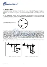
The fusite connections are marked as in Figure 7. Recommended wiring diagrams are shown in Figure 8 and Figure
9. Single-phase compressors are connected to the common (C), start (S) and run (R) connections as usual. Three-
phase models are connected (L1,L2,L3) to T1, T2 and T3.
C
S
R
T1
T3
T2
E.2.09.00
Figure 7: Motor terminal connections
Scroll compressors, like several other types of compressors, will only compress in one rotational direction. Direction of
rotation is not an issue with single-phase compressors since they will always start and run in the proper direction
(except as described in Section 16). However, three-phase compressors will rotate in either direction depending upon
phasing of the power to L1, L2 and L3. Since there is a 50/50 chance of connecting power in such a way as to cause
rotation in the reverse direction, it is important to include notices and instructions in appropriate locations on the
equipment to ensure proper rotation direction is achieved when the system is installed and operated. Verification of
proper rotation direction is made by observing that suction pressure drops and discharge pressure rises when the
compressor is energized. Reverse rotation results in a sound level above that with correct rotation direction, as well
as substantially reduced current draw compared to tabulated values and after several minutes of operation the
compressor’s internal protector will trip.
All three-phase compressors are wired identically internally. As a result, once the correct phasing is determined for a
specific system or installation, connecting properly phased power leads to the same terminals should maintain proper
rotation direction.
L1
M
3
L2
L3
K1
F6...8
F1
L1 N
L1
L2
L3
N
PE
Q1
Control circuit
E.1.04.00
R
M
1
C
S
K1
F6
F1
L1 N
L1
N
PE
Q1
Control circuit
C2
E.1.03.00
Figure 8: Power circuit single phase
Figure 9:
Power circuit three phase
C6.2.9/0203-1004/E 7

