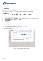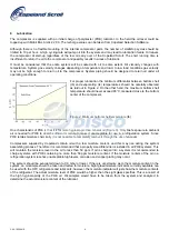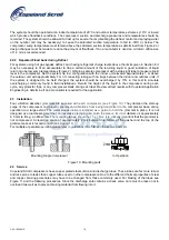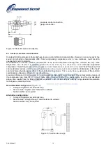
The entire chain is internally led to the fusite from where it is connected to the module connections S1 and S2 (see
Figure 9). When any resistance of the thermistor chain reaches the tripping value, the module interrupts the control
line and causes the compressor to switch off. After the thermistor has cooled sufficiently, its resistance drops to the
reset value but the module itself resets after a time delay of 30 minutes and restarts the compressor.
19 Protector Functional Check and Failure Detection
Prior to start-up of the compressor a functional check shall be carried out:
Switch off power!
Disconnect one terminal either S1 or S2 of the electronic module. If the compressor is now switched on, the
motor should not start.
Switch off power.
Reconnect the disconnected thermistor line. If the compressor is now switched on the motor must start.
Protector Fault Diagnosis:
If the motor does not start-up during the functional check, this indicates a disturbance in operation:
Switch off power.
Check the connection of the thermistor leads in the terminal box and at the protection module for possible
loose connections and check the connection cable for possible breakage.
The resistance of the thermistor chain shall be measured in a cold condition, i.e. after the motor has
sufficiently cooled down.
Caution:
Use maximum measuring voltage of 3 V!
In doing so, the thermistor leads at terminals S1 and S2 of the module shall be disconnected and measured between
the leads. Resistance must be between 150 and 1250 ohms.
If the thermistor chain has a higher resistance (2750 Ohms or greater) the motor temperature is still too high and it
has to be allowed to cool.
If the resistor is 0 Ohms, the compressor has to be exchanged due to shorted sensor circuit.
∞
Ohms indicates an
open sensor circuit and the compressor has to be replaced.
If no defect is located in the thermistor chain or there is no loose contact or conductor breakage, the module shall be
checked. Then the control connections at M1 and M2 have to be removed (
Caution!
Switch off voltage supply first!)
and check the switching conditions by an ohm-meter or signal buzzer:
short-cut the already disconnected thermistor contactors S1 and S2 and switch on the voltage supply; the
relay must switch; connection established between contactors M1 and M2
remove the jumper between S1 and S2, the relay must switch off; no connection between contactors M1 and
M2
short-cut the contactors S1 and S2 again, the relay remains switched off; no connection between contactors
M1 and M2
switch off the voltage supply for approximately 4 sec and switch it on again, the relay must switch on now;
connection between contactors M1 and M2
If one of the above conditions is not met, the module is defective and has to be exchanged.
Note
: The power should be switched off between the tests, in order to avoid short circuits and accidental touching of
contacts. The function of the module should be tested each time the fuse in the control circuit breaks the power
supply. This makes sure that the contacts did not stick.
C6.2.16/1004/E 8


