background image


20  High Potential Testing 

Copeland subjects all motor compressors to a high voltage test after final assembly. This is carried out according to 
IEC-34-1. 
Since high voltage tests lead to premature aging of the winding insulation we do not recommend additional tests of 
that nature. They may also be carried out with new machines only. 
If it has to be done for any reason disconnect all electronic devices (e.g. motor protection module, fan speed control, 
etc.) prior to testing. The test voltage of 1000 V plus twice the nominal voltage is applied for 1 - 4 seconds between 
motor winding (each one of the phases) and the compressor shell: The maximum leak current limit is approximately 
10 mA. Repeated tests have to be performed at lower voltages. 
 

Caution

: Do not carry out high voltage or insulation tests if the compressor housing is under vacuum. Copeland Scroll 

compressors are configured with the motor down and the pumping components at the top of the shell. As a result, the 
motor can be immersed in refrigerant to a greater extent than hermetic reciprocating compressors when liquid 
refrigerant is present in the shell. In this respect, the scroll is more like semi-hermetics (which have horizontal motors 
partially submerged in oil and refrigerant). When Copeland Scroll compressors are high potential tested with liquid 
refrigerant in the shell they can show higher levels of leakage current than compressors with the motor on top 
because of the higher electrical conductivity of liquid refrigerant than refrigerant vapour and oil. However, this 
phenomenon can occur with any compressor when the motor is immersed in refrigerant. The levels of current leakage 
do not present any safety issue. To lower the current leakage reading the system should be operated for a brief 
period of time to redistribute the refrigerant to a more normal configuration and the system high potential tested again. 
 

21  Compressor Functional Check 

It is not desirable to perform functional compressor tests where the compressor is turned on with the suction service 
valve closed to check how low the compressor will pull suction pressure. Rather, the following diagnostic procedure 
should be used to evaluate whether the Copeland Scroll compressor is functioning properly. 
 

1.  Proper voltage to the unit should be verified. 
2.  The normal checks of motor winding continuity and short to ground should be made to determine if an internal 

motor short or ground fault has developed. If the protector has opened, the compressor must be allowed to 
cool sufficiently to allow it to reset. 

3.  Proper indoor and outdoor fan/blower operation should be verified. 
4.  With service gauges connected to suction and discharge pressure fittings, turn on the compressor. If suction 

pressure falls below normal levels the system is either low on charge or there is a flow blockage in the 
system. 

5.  If suction pressure does not drop and discharge pressure does not rise to normal levels, reverse any two of 

the compressor power leads and reapply power to make sure compressor was not wired to run in reverse 
direction. If pressures still do not move to normal values, the compressor is faulty. 


22  Excessive Liquid Floodback 

The following tests are for those Air/Water system configurations and charge levels, which need special testing to 
verify exemption from the need of an accumulator.  
 

22.1 Continuous 

Floodback 

To test for excessive continuous liquid refrigerant floodback, it is necessary to operate the system in a test room at 
conditions where steady state floodback may occur (low ambient air/water heating). Thermocouples should be 
attached to the suction and discharge lines of the compressor (approximately 150 mm from the shell) and insulated. If 
the system is designed to be field charged it should be overcharged by 15 % in this test to simulate overcharging 
commonly found in field installations.  

C6.2.16/1004/E 9 

Summary of Contents for Copeland Scroll ZH56 K4E ZH11 ME Series

Page 1: ...Scroll compressors for Dedicated Heat Pumps ZH56 K4E ZH11 ME Application Guidelines ...

Page 2: ...nt Cut Out 6 13 Pressure Controls 6 14 Shut off Sound 6 15 Starting 6 16 Deep Vacuum Operation 6 17 Electrical Installation 6 18 Electronic Motor Protection 7 19 Protector Functional Check and Failure Detection 8 20 High Potential Testing 9 21 Compressor Functional Check 9 22 Excessive Liquid Floodback 9 22 1 Continuous Floodback 9 22 2 Repeated Flood back during Defrost 10 23 Installation 10 24 S...

Page 3: ... start the compressor until it is charged with refrigerant Correctly used the compressor and the pressure line piping may reach temperatures that may cause burning if touched Wear safety goggles when working on open systems If the refrigerant needs to be removed from the system do not disperse it in the environment use the correct equipment method of removal For storage use original packaging and ...

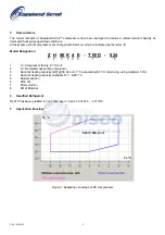
Page 4: ... 524 1 2 3 4 5 6 7 8 1 Z Compressor family Z Scroll 2 H Dedicated heat pump compressor 3 Nominal heating capacity kW 50 Hz and 7 C evaporating 50 C condensing using multiplier 1 3rd 4 Nominal heating capacity multiplier K 1 M 10 5 Model variation 6 POE Oil 7 Motor version 8 Bill of Material 4 Qualified Refrigerant R407C has been qualified for the compressor models ZH56K4E ZH11ME 5 Application Enve...

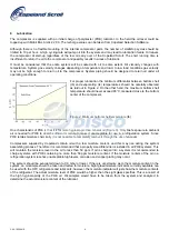
Page 5: ...l temperature tb One characteristic of POE is that it is far more hygroscopic than mineral oil Figure 3 Only brief exposure to ambient air is needed for POE to absorb sufficient moisture to make it unacceptable for use in a refrigeration system Since POE retains moisture chemically it is not possible to completely remove it through the use of vacuum Compressors supplied by Copeland contain oil wit...

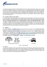
Page 6: ...grating into the shell during standstill periods It is recommended to fit a CCH if the compressor is located outside the building the system charge is above the limits shown For correct mounting location of a CCH please see Figure 5 Fig 5 Crankcase heater location 9 Screens The use of screens finer than 30 x 30 mesh 0 6 mm openings anywhere in the system is not recommended Field experience has sho...

Page 7: ...e tube of the compressor prevents high pressure gas entering the compressor after shut down Additionally there is a dynamic discharge valve mounted on the fixed Scroll which effectively eliminates reverse rotation 15 Starting During the very brief start up a short metallic sound is audible resulting from initial contacting of the spirals and is normal Due to the design of the Copeland Scroll the i...

Page 8: ...series is embedded in the motor windings so that the temperature of the thermistors can follow the winding temperature with little inertia An electronic module is required to process the resistance values and trip a control relay depending on the thermistor resistance The characteristic gradient of a thermistor resistance curve is shown in Figure 8 The resistance curve can be designed for differen...

Page 9: ...onnected and measured between the leads Resistance must be between 150 and 1250 ohms If the thermistor chain has a higher resistance 2750 Ohms or greater the motor temperature is still too high and it has to be allowed to cool If the resistor is 0 Ohms the compressor has to be exchanged due to shorted sensor circuit Ohms indicates an open sensor circuit and the compressor has to be replaced If no ...

Page 10: ... configuration and the system high potential tested again 21 Compressor Functional Check It is not desirable to perform functional compressor tests where the compressor is turned on with the suction service valve closed to check how low the compressor will pull suction pressure Rather the following diagnostic procedure should be used to evaluate whether the Copeland Scroll compressor is functionin...

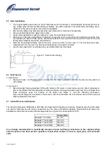
Page 11: ...f the liquid in the compressor during each cycle any protector trips or any compressor stalls during each test Review all test results with Copeland Application Engineering to determine if an accumulator is required for the application 23 Installation Four vibration absorber grommets are supplied with each compressor see Figure 10 They dampen the start up surge of the compressor and prevent sounds...

Page 12: ... joint areas 2 and 3 slowly and uniformly until the braze material softens and the tube can be pulled out of the fitting To reconnect Recommended brazing materials Silfos with minimum 5 silver or silver braze used on other compressors Due to the different thermal properties of steel and copper brazing procedures may have to be changed from those commonly used For brazing of the tubes see Figure 11...

Page 13: ...ion line into a house under some conditions Elimination of the beat can be achieved by attenuating either of the contributing frequencies This is easily done by using one of the common combinations of design configuration described below A second difference of the Copeland Scroll compressor is that under some conditions the normal starting motion of the compressor can transmit an impact noise alon...

Page 14: ...hell and suction line tubing pressurised If a brazing torch is then applied to the low side while the low side shell and suction line contains pressure the pressurised refrigerant and oil mixture could ignite when it escapes and contacts the brazing flame To prevent this occurrence it is important to check both the high and low side with manifold gauges before unbrazing Instructions should be prov...

Page 15: ...Notes ...

Page 16: ...a D 63477 Maintal P 02 673 Warszawa Tel 49 0 6109 6059 0 Tel 48 225 458 9205 Fax 49 0 6109 6059 40 Fax 48 225 458 9255 France Greece Maghreb Russia CIS 8 Allee Du Moulin Berger Malaya Trubetskaya 8 11th Floor F 69130 Ecully RUS 119881 Moscow Tel 33 0 4 78668570 Tel 7 095 232 94 72 Fax 33 0 4 78668571 Fax 7 095 232 03 56 Italia Middle East Africa Via Ramazzotti 26 PO Box 26382 R A 8 FD 2 I 21047 Sa...

Reviews: