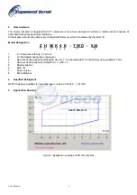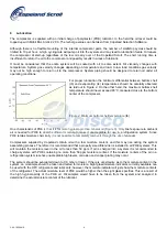
The system should be operated at an indoor temperature of 20°C and outdoor temperature extremes (-18°C or lower)
which produce floodback conditions. The compressor suction and discharge pressures and temperatures should be
recorded. The system should be allowed to frost up for several hours (disabling the defrost control and spraying water
on the outdoor coil may be necessary) to cause the saturated suction temperature to fall to -30°C or below. The
compressor sump temperature must remain above the saturated suction temperature as determined from Figure 2 or
design changes must be made to reduce the amount of floodback. If an accumulator is used an oil return orifice size
of 1,4 mm is recommended.
22.2 Repeated Flood back during Defrost
For systems using hot gas bypass defrost, and having refrigerant charge levels above the limits given in Section 8 it
may be necessary to fit an accumulator to trap a certain amount of the returning liquid. A good indication of liquid
return can be low sump temperatures (Figure 2). Obtain a sample compressor with a side sight tube to measure liquid
level in the compressor. Set the system up in a configuration with the indoor unit elevated approximately 1 m above
the outdoor unit with approximately 7 m of connecting tubing with no traps between the indoor and outdoor units. If
the system is designed to be field charged, the system should be overcharged by 15% in this test to simulate
overcharging commonly found in field installations. Record the height of the liquid in the compressor during each
cycle, any protector trips, or any compressor stalls during each test. Review all test results with Copeland Application
Engineering to determine if an accumulator is required for the application.
23 Installation
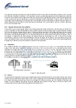
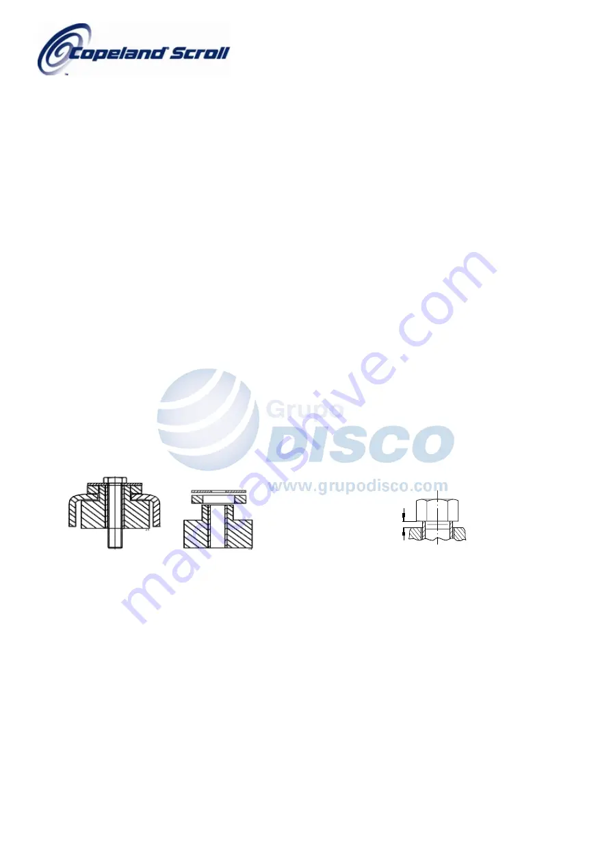
Four vibration absorber grommets are supplied with each compressor (see Figure 10). They dampen the start-up
surge of the compressor and prevent sounds and vibrations from being transmitted to the compressor base during
operation to a large extent. The metal sleeve inside is intended as a guide to hold the grommet in place. It is not
designed as a load-bearing member, and excessive torquing can crush the sleeve. Its inner diameter is approximately
8.5 mm to fit e.g. an M8 screw. The mounting torque should be 13 ± 1 Nm. It is critically important that the grommet is
not compressed. A clearance space of approximately 2 mm between the bottom of the washer and the top of the
grommet spacer is recommended (see Figure. 10)
For multiple or parallel operation please refer to guidelines C6.2.5/E and the spares parts list.
Z.9.28.00
2 mm
Mounting
Single
Compressor
In
Operation
Figure 10: Mounting parts
24 Service
Copeland Scroll compressors have copper plated steel suction and discharge tubes. These tubes are far more robust
and less prone to leaks than copper tubes used on other compressors. Due to the different thermal properties of steel
and copper, brazing procedures may have to be changed from those commonly used. For brazing of the tubes see
Figure 11 and the following procedures. Since the discharge stub contains a check valve, care must be taken not to
overheat it as well as to prevent brazing material from flowing into it.
C6.2.16/1004/E 10


