


Summary of Contents for Copeland Scroll ZR108KRE
Page 4: ...AGL_AC_ST_ZRKRE_E_Rev01 DISCLAIMER 34 ...
Page 5: ......
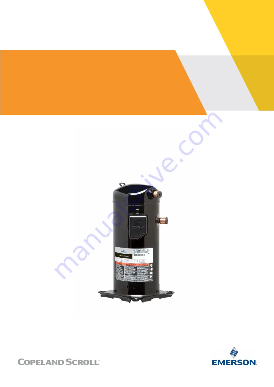
The Emerson Copeland Scroll ZR108KRE is a high-performance air conditioning compressor. Ensure smooth installation and usage with our comprehensive Application Manual offering step-by-step instructions and troubleshooting tips. Download this manual for free at 88.208.23.73:8080 and optimize your product's performance effortlessly.
Page 4: ...AGL_AC_ST_ZRKRE_E_Rev01 DISCLAIMER 34 ...
Page 5: ......


