16
C6.2.41/0219/E
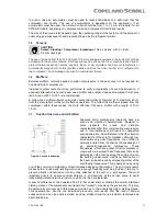
If a crankcase heater is fitted it is recommended that
the heater be turned on for a
minimum of 12 hours
prior to starting the compressor. This will prevent oil
dilution and bearing stress on initial start up. The
crankcase heater must remain energised during
compressor off cycles.
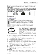
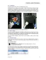
The crankcase heater must be mounted below the oil
schraeder valve located on the bottom shell (see
Figure 12
).
Figure 12: Crankcase heater location
4.3
Pressure safety controls
4.3.1 High-pressure control
The cut-out setting for the high-pressure control shall be determined according to regional
standards, usually EN 378, part 2 in Europe.
The maximum pressure value for the individual compressor type, PS high side, is printed on the
nameplate of the compressor.
The high-pressure cut-out should have a manual reset feature for the highest level of system
protection.
4.3.2 Low-pressure control
The minimum cut-out setting shall be determined according to the refrigerant and to the allowed
operation envelope
– see technical data in Select software at
www.climate.emerson.com/en-gb
.
For example, a minimum cut-out setting of 0.5 bar(g) is required for ZR compressors using R513A.
The low-pressure cut-out should have a manual reset feature for the highest level of system
protection.
4.3.3 Internal pressure relief valve
There is an internal pressure relief valve on all ZR24KRE to ZR92KRE scroll compressors, which
opens at a differential pressure of 28 bar ± 3 bar between high- and low-pressure sides. A high-
pressure cut-out may be required according to national regulations and is strongly recommended
due to the capabilities of pumping to high pressures once the discharge is obstructed.
The IPR valve is a safety device, not an HP switch. It is not designed for repeated operation and
there is no guarantee that it will reset correctly if it does have repeated operation.
4.4
Discharge temperature protection
The use of an external discharge thermostat is required for compressor model ZR92KRE.
A discharge thermostat can be used but is not mandatory for compressor models ZR24KRE to
ZR81KRE because these models have an internal thermodisc which is positioned next to the
discharge port of the scroll set. When the thermodisc opens, a small gas by-pass occurs which
trips the Klixon motor protector. The internal thermodisc opens at 146°C ± 4K and closes at
91°C ± 7K.
Internal discharge temperatures can reach unacceptable values under some extreme operating
conditions (such as loss of refrigerant injection charge or extremely high compression ratio). This
could cause compressor damage.
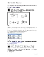
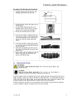
The discharge thermostat dedicated to R450A and R513A has a cut-out setting of 130°C ± 4K
with closing at 101°C ± 8K and should be installed approximately 120 mm from the discharge
valve outlet (see assembly instructions below).
To ensure proper functioning and to avoid false readings, the discharge line thermostat must be
installed and insulated according to the procedure and recommendations hereunder.

