background image


12 


C6.3.1/0116-0716/E 

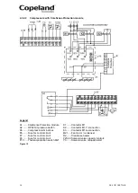
4.3.1.2 

Compressors with CoreSense Protection module 


Legend 

A1 ....... CoreSense Protection module 

K1 ........ Contactor M1 

A2 ....... OPS2 Oil pressure switch  

K4 ........ Contactor M1 for second part-winding 

A5 ....... Compressor terminal box 

M21 ..... Fan motor / condenser 

F6 ....... Fuse for control circuit 

R2 ........ Crankcase heater 

F7 ....... Fuse for control circuit  

Y21 ...... Solenoid valve capacity control 1 

F8 ....... Fuse for control circuit  

Y22 ...... Solenoid valve capacity control 2 

F10 ..... Thermal protection switch M21 

Y3 ........ Solenoid valve unloaded start 

Figure 10 


Summary of Contents for Copeland Stream 4MA-22X

Page 1: ...Application Guidelines Copeland Stream Semi Hermetic Compressors 4MF 13X to 4MK 35X 6MM 30X to 6MK 50X ...

Page 2: ... 5 2 6 3 Demand cooling 5 2 6 4 Unloaded start 5 2 6 5 Capacity control 5 2 6 6 Oil pumps 6 2 6 7 Oil pressure 6 2 6 8 Oil circulation 6 2 6 9 Oil level 6 3 Installation 7 3 1 Compressor handling 7 3 1 1 Delivery 7 3 1 2 Transport and storage 7 3 1 3 Positioning and securing 7 3 1 4 Installation location 8 3 1 5 Mounting parts 8 3 2 Pressure safety controls 8 3 2 1 High pressure control 8 3 2 2 Lo...

Page 3: ...rting up operation 19 5 1 Leak test 19 5 2 System evacuation 19 5 3 Preliminary checks Pre starting 19 5 4 Charging procedure 19 5 5 Initial start up 20 5 6 Minimum run time 20 5 7 Recommended inverter range 20 6 Maintenance repair 21 6 1 Exchanging the refrigerant 21 6 2 Replacing a compressor 21 6 3 Lubrication and oil removal 21 6 4 Oil additives 22 6 5 Unbrazing system components 22 7 Dismantl...

Page 4: ...on indicates operations with a danger of explosion 1 2 Safety statements Refrigerant compressors must be employed only for their intended use Only qualified and authorized HVAC or refrigeration personnel are permitted to install commission and maintain this equipment Electrical connections must be made by qualified electrical personnel All valid standards for connecting electrical and refrigeratio...

Page 5: ...e equipment gloves eye protection etc must be used at all times POE must not come into contact with any surface or material that might be harmed by POE including without limitation certain polymers eg PVC CPVC and polycarbonate IMPORTANT Transit damage Compressor malfunction Use original packaging Avoid collisions and tilting ...

Page 6: ...re2 High temperature1 Low temperature3 Displacement m3 h Nominal horsepower hp Model 62 381 x 305 71 78 88 99 120 135 153 R404A R134a R404A Net weight kg 1 R134a Evaporating 5 C condensing 50 C suction superheat 10K subcooling 0K 2 R404A Evaporating 10 C condensing 45 C suction gas temperature 20 C subcooling 0K 3 R404A Evaporating 35 C condensing 40 C suction gas temperature 20 C subcooling 0K Ta...

Page 7: ...mended the use of a crankcase heater is mandatory retrofit to R450A and R513A is only allowed for compressors which are approved for these refrigerants Contact Application Engineering for any further information IMPORTANT It is essential that the glide of refrigerant blends primarily R407C is carefully considered when adjusting pressure and superheat controls Oil recharge values can be taken from ...

Page 8: ...njection on demand For low temperature applications with R407F R407A R448A R449A and R22 Demand Cooling can be required on the following compressors 4MF 13X 4ML 15X 4MM 20X 4MT 22X 4MU 25X 6MM 30X 6MT 35X 6MU 40X NOTE R22 is no longer allowed for new refrigeration systems in Europe 2 6 4 Unloaded start With direct starting the motor of a compressor is switched directly into the mains by means of a...

Page 9: ...ses on compressor start up due to the pressure difference arising between motor side and crankcase thus slowing down pressure decrease in the crankcase over a certain period of time It reduces the foaming of the oil refrigerant mixture that would occur if the pressure decreased rapidly The valve does not reopen until the pressure has been equalized by means of a crankcase ventilating valve This se...

Page 10: ... not stack pallets on top of each other Keep the packaging dry at all times Figure 4 Compressors are delivered on pallets Cooling fans are delivered in separate boxes Accessories may be mounted or delivered loose Solenoid valves are never mounted 3 1 3 Positioning and securing IMPORTANT Handling damage Compressor malfunction Only use the lifting eyes whenever the compressor requires positioning Us...

Page 11: ...ted by the rack and or the compressor bottom plate feet Excessive unevenness can result in too high mechanical stress to the system and could damage the compressor or rack Therefore the flatness of the mounting location is essential In addition both vibration shock and mechanical stress to compressor can be avoided by using rubber mounting parts If the installation requires a very high level of vi...

Page 12: ... 1 As the tube approaches brazing temperature move the torch flame to area 2 Heat area 2 until braze temperature is attained moving the torch up and down and rotating around the tube as necessary to heat the tube evenly Add braze material to the joint while moving the torch around the joint to flow braze material around the circumference After the braze material flows around the joint move the tor...

Page 13: ...s YY Y Code A Part winding motors contain two separate windings 2 3 1 3 which are internally connected in star and operated in parallel You cannot change the voltage by changing the electrical connections as the motor is only suitable for one voltage The first part winding ie the 2 3 winding on terminals 1 2 3 can be used for part winding start remove the bridges After a time delay of 1 0 1 second...

Page 14: ...ors with CoreSense Diagnostics module Legend A4 Sensor module K1 Contactor M1 A5 Compressor terminal box K4 Contactor M1 for second part winding CCH Crankcase heater M21 Fan motor condenser F6 Fuse for control circuit R2 Crankcase heater F7 Fuse for control circuit Y21 Solenoid valve capacity control 1 F8 Fuse for control circuit Y22 Solenoid valve capacity control 2 F10 Thermal protection switch ...

Page 15: ...witch K4 Contactor M1 for second part winding A5 Compressor terminal box M21 Fan motor condenser F6 Fuse for control circuit R2 Crankcase heater F7 Fuse for control circuit Y21 Solenoid valve capacity control 1 F8 Fuse for control circuit Y22 Solenoid valve capacity control 2 F10 Thermal protection switch M21 Y3 Solenoid valve unloaded start Figure 10 ...

Page 16: ...Diagnostics module Legend A4 Sensor module K1 Contactor M1 A5 Compressor terminal box K2 Contactor M1 Y connection CCH Crankcase heater K3 Contactor M1 Δ connection F6 Fuse for control circuit M21 Fan motor condenser F7 Fuse for control circuit R2 Crankcase heater F8 Fuse for control circuit Y21 Solenoid valve capacity control 1 F10 Thermal protection switch M21 Y22 Solenoid valve capacity control...

Page 17: ...ressure switch K2 Contactor M1 Y connection A5 Compressor terminal box K3 Contactor M1 Δ connection F6 Fuse for control circuit M21 Fan motor condenser F7 Fuse for control circuit R2 Crankcase heater F8 Fuse for control circuit Y21 22 Solenoid valve capacity controls F10 Thermal protection switch M21 Y3 Solenoid valve unloaded start Figure 12 ...

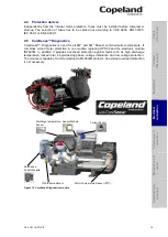
Page 18: ... and the electronic module INT69TM In addition it provides advanced protection against faults such as high discharge temperature locked rotor single missing phase voltage imbalance and low voltage protection The module is capable of communication via Modbus protocol An external overload protection is not necessary Figure 13 CoreSense Diagnostics module Discharge temperature Sensor Oil Pressure Sen...

Page 19: ...wo chains of three thermistors each connected in series are embedded in the motor windings in such a manner that the temperature of the thermistors can follow with little inertia The CoreSense Protection module switches a control relay depending on the thermistor resistance It is installed in the terminal box to which the thermistors are connected Caution The maximum test voltage for thermistors i...

Page 20: ...e same wires can be applied to the OPS2 which will give the functions of an OPS1 module To obtain use of all of the features of the OPS2 a 7 wire cable between the electrical control cabinet and the compressor terminal box should be used Wiring diagrams for OPS2 are shown in Technical Information D7 8 3 DWM Copeland Semi hermetic Compressor Oil Pressure Differential Switch OPS2 available at www em...

Page 21: ... A5 Compressor terminal box R Relay N Neutral connection t Time delay Figure 17 Protection class IP30 4 7 Crankcase heaters IMPORTANT Oil dilution Bearing malfunction Turn the crankcase heater on 12 hours before starting the compressor A crankcase heater is used to prevent refrigerant from migrating into the shell during standstill periods Heaters for 4M and 6M compressors are screwed into a sleev...

Page 22: ...essure about 1 to 2 5 bar this is to indicate that the compressor does not leak When removing plugs from the compressor in order to connect a pressure gauge or to fill in oil the plug may pop out under pressure and oil can spurt out 5 3 Preliminary checks Pre starting Discuss details of the installation with the installer If possible obtain drawings wiring diagrams etc It is ideal to use a check l...

Page 23: ...l gaskets should be oiled before fitting O rings should also be oiled NOTE A compressor should never be operated beyond its approved application range Check by consulting the appropriate data sheet To avoid motor damage the compressor MUST NOT be started nor may high potential testing be carried out under vacuum 5 6 Minimum run time Emerson Climate Technologies recommends a maximum of 10 starts pe...

Page 24: ... This is because the accumulator oil return orifice or screen may be plugged with debris or may become plugged shortly after a compressor failure This will result in starvation of oil to the replacement compressor and a second failure When a single compressor or tandem is exchanged in the field it is possible that a major portion of the oil may still be in the system While this may not affect the ...

Page 25: ...g term chemical stability of any additive in the presence of refrigerant low and high temperatures and materials commonly found in refrigeration systems is complex and difficult to evaluate without rigorously controlled chemical laboratory testing The use of additives without adequate testing may result in malfunction or premature failure of components in the system and in specific cases in voidin...

Page 26: ... Ø 25 5 mm 5 Crankcase heater 2 Magnetic plug 1 16 UN 6 Plug oil charge 1 4 3 Oil sight glass 1 4 20 UNC 7 Plug high pressure connection 1 8 4 Plug low pressure connection 1 8 6M 6MM 30X 6MT 35X 6MU 40X 6MI 40X 6MJ 45X 6MK 50X SL Suction line size sweat 6MM30X 6MT35X 6MI40X 6MJ45X Ø 2 1 8 DL Discharge line size sweat 6MT35X 6MU 40X 6MJ45X 6MK 50X Ø 1 5 8 SL Suction line size sweat 6MK50X 6MU40X Ø ...

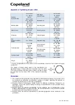
Page 27: ...he piston con rod assemblies clean the Torx screws and apply Loctite 2701 The ranges of torque values given in this specification are assembly torques Torque after joint relaxation must be within 15 of the minimum assembly torque unless re torque is called for and must not be above 10 of the maximum assembly torque Disclaimer 1 The contents of this publication are presented for informational purpo...

Page 28: ... 971 4 811 81 00 Fax 971 4 886 54 65 mea sales emerson com ASIA PACIFIC Suite 2503 8 25 F Exchange Tower 33 Wang Chiu Road Kowloon Bay Kowloon Hong Kong SPAIN PORTUGAL C Pujades 51 55 Box 53 ES 08005Barcelona Tel 34 93 412 37 52 Fax 34 93 412 42 15 iberica sales emerson com RUSSIA CIS Emerson LLC Dubininskaya str 53 build 5 4th floor 115054 Moscow Russia Phone 7 495 995 95 59 Fax 7 495 424 88 50 R...

Reviews: