C6.3.1/0116-0716/E
11
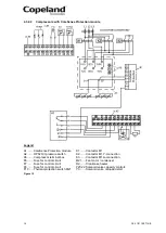
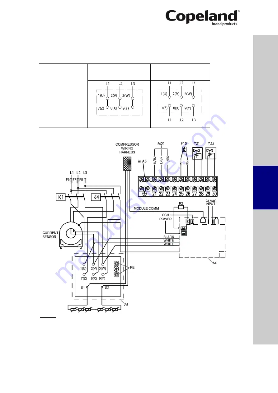
4.3.1 Wiring diagram for part-
winding motors (AW…)
Part winding motors can be connected direct-on-line or part-winding start.
NOTE: The sensor module inside the terminal box requires a separate 24V AC power
supply.
Part-winding motor:
Y
– Y
Code A
Direct-on-line start
Y - Y
Part-winding start
First start step 1
–2-3
Y - Y
4.3.1.1
Compressors with CoreSense Diagnostics module
Legend
A4 ....... Sensor module
K1 ........ Contactor M1
A5 ....... Compressor terminal box
K4 ........ Contactor M1 for second part-winding
CCH .... Crankcase heater
M21 ..... Fan motor / condenser
F6 ....... Fuse for control circuit
R2 ........ Crankcase heater
F7 ....... Fuse for control circuit
Y21 ...... Solenoid valve capacity control 1
F8 ....... Fuse for control circuit
Y22 ...... Solenoid valve capacity control 2
F10 ..... Thermal protection switch M21
Figure 9
S
afet
y
in
struct
ion
s
P
ro
d
u
ct
d
es
cr
ipt
ion
Inst
all
atio
n
E
lec
tr
ica
l
c
o
n
n
ec
tion
S
tar
ting
up
&
o
p
er
atio
n
Ma
int
enan
c
e &
repai
r
Dismant
ling
&
d
ispo
sa
l


