C6.3.2/0416-0716/E
13
4
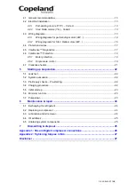
Electrical connection
4.1 General recommendations
The compressor terminal box has a wiring diagram on the inside of its cover. Before connecting
the compressor, ensure the supply voltage, the phases and the frequency match the nameplate
data.
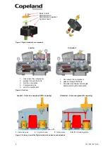
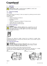
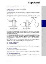
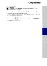
The knockouts have to be removed before the electrical glands can be installed. First make sure
that the terminal box is closed with the terminal box cover. We recommend to use a subland
twist driller to avoid any damage to the box while removing the knockouts.
Figure 12
4.2 Electrical installation
All compressors can be started Direct-on-line.
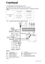
The position of bridges required for Direct-on-line start (depending on type of motor and/or mains
voltage) is shown in Chapter 4.3 "Wiring diagrams".
4.2.1 Part-winding motors (YY/Y)
– Code A
Part-winding motors contain two separate windings (2/3 + 1/3) which are internally connected in
star and operated in parallel. You cannot change the voltage by changing the electrical
connections as these motors are only suitable for one voltage.
The first part winding, ie, the 2/3 winding on terminals 1-2-3, can be used for part-winding start
(remove the bridges!). After a time delay of 1 ± 0.1 seconds the second part winding, ie, the 1/3
winding on terminals 7-8-9, must be brought on line.
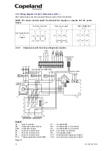
4.2.2 Star / Delta motors
(Y/∆) – Code E
Star / Delta motors are
interchangeable for star (Y) or delta (∆) operation by means of bridges.
They are suitable for two voltages, eg, 230V in delta, 400V in star connection. If the supply
voltage and the nominal voltage of the motor in ∆-connection are identical, the star connection
motor can also be used for starting (remove the bridges!).
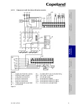
4.3 Wiring diagrams
The position of the jumpers in the terminal box and the recommended wiring diagrams are
shown in
Figures 13 to 16
.
S
afet
y
in
struct
ion
s
P
ro
d
u
ct
d
es
cr
ipt
ion
Inst
all
atio
n
E
lec
tr
ica
l
c
o
n
n
ec
tion
S
tar
ting
up
&
o
p
er
atio
n
Ma
int
enan
c
e &
repai
r
Dismant
ling
&
d
ispo
sa
l
Twist driller


