Memory Maps and Addresses
CPCI-6200 Installation and Use (6806800J66C)
141
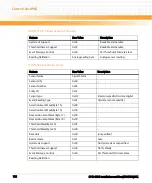
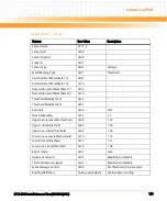
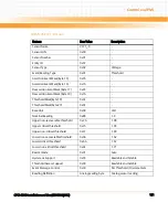
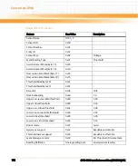
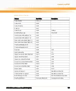
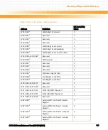
F200 0020
3
Watchdog Timer Load
3
F200 0021
1
Reserved
3
F200 0022
1
Reserved
3
F200 0023
1
Reserved
3
F200 0024
3
Watchdog Timer Control
3
F200 0025
3
Watchdog Timer Resolution
3
F200 0026
3
Watchdog Timer Count (16 bits)
3
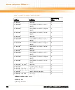
F200 0028—F200 002F
1
Reserved
3
F200 0030
3
PLD Revision
3
F200 0031
1
Reserved
3
F200 0032
1
Reserved
3
F200 0033
1
Reserved
3
F200 0034
3
PLD Date Code (32 bits)
3
F200 0038
3
Test Register 1 (32 bits)
3
F200 003C
3
Test Register 2 (32 bits)
3
F200 0040—F200 FFFF
1
Reserved
3
F201 0000—F201 2FFF
1
Reserved
4
F201 3000—F201 3FFF
COM 3 (DUART channel 1)
4
F201 4000—F201 4FFF
COM 4 (DUART channel 2)
4
F201 5000—F201 FFFF
1
Reserved
F202 0000
2
External PLD Tick Timer Prescaler
Register
5
F202 0010
2
External PLD Tick Timer 1 Control
Register
5
F202 0014
2
External PLD Tick Timer 1 Compare
Register
5
F202 0018
2
External PLD Tick Timer 1 Counter
Register
5
Table 7-4 System I/O Memory Map (continued)
Address
Definition
LBC Bank/Chip
Select
Summary of Contents for CPCI-6200
Page 14: ...CPCI 6200 Installation and Use 6806800J66C 14 List of Figures ...
Page 20: ...CPCI 6200 Installation and Use 6806800J66C About this Manual 20 About this Manual ...
Page 28: ...Introduction CPCI 6200 Installation and Use 6806800J66C 28 ...
Page 44: ...Hardware Preparation and Installation CPCI 6200 Installation and Use 6806800J66C 44 ...
Page 70: ...Controls LEDs and Connectors CPCI 6200 Installation and Use 6806800J66C 70 ...
Page 106: ...MOTLoad Firmware CPCI 6200 Installation and Use 6806800J66C 106 ...
Page 178: ...Memory Maps and Addresses CPCI 6200 Installation and Use 6806800J66C 178 ...
Page 195: ......


