Controls, LEDs, and Connectors
CPCI-6200 Installation and Use (6806800J66C
)
64
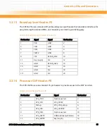
3.3.13 IPMI Debug and FW Programming Header, P3
The CPCI-6200 provides one 4-pin planar header connected to IPMI serial port 2 for debugging
and programming IPMI firmware.
3.3.14 Processor Debug Header, P4
The CPCI-6200 has a 10-pin header for debugging. This header can debug a DDR or LBC
interface.
Table 3-13 IPMI Debug Pinout, P3
Pin Number
Signal
1
TXD
2
GND
3
RXD
4
GND
Table 3-14 Processor Debug Header Pinout, P4
Pin Number
Signal
Signal
Pin Number
1
GND
MCRCID_0
2
3
TRIG_IN
MCRCID_1
4
5
TRIG_OUT
MCRCID_2
6
7
MDVAL
MCRCID_3
8
9
3.3V
MCRCID_4
10
Summary of Contents for CPCI-6200
Page 14: ...CPCI 6200 Installation and Use 6806800J66C 14 List of Figures ...
Page 20: ...CPCI 6200 Installation and Use 6806800J66C About this Manual 20 About this Manual ...
Page 28: ...Introduction CPCI 6200 Installation and Use 6806800J66C 28 ...
Page 44: ...Hardware Preparation and Installation CPCI 6200 Installation and Use 6806800J66C 44 ...
Page 70: ...Controls LEDs and Connectors CPCI 6200 Installation and Use 6806800J66C 70 ...
Page 106: ...MOTLoad Firmware CPCI 6200 Installation and Use 6806800J66C 106 ...
Page 178: ...Memory Maps and Addresses CPCI 6200 Installation and Use 6806800J66C 178 ...
Page 195: ......

