Page 11
Product Information / Produktinformation
A6151
Shaft Vibration Monitor
1
3
5
2
4
6
1
3
5
2
4
6
a)
b)
i
For trouble
−
free operation of the RS 485 bus, the lines “A” and “B” must be
connected on their references (+5 V, ground) in one monitor. This is only
possible if the bus termination jumper at this monitor has been closed as well.
1.5.2 Sensor raw signal
The raw sensor signal (unfiltered, in
−
phase output signal of the converter with AC and DC
portion) is applied to the front panel SMB sockets and can be fed to the terminals
z14
: channel
1 and
z16
: channel 2 of the connection strip with the jumpers J2. As delivered, the J2 jumpers
are set, that on terminals z14 and z16 the dynamic portion of the sensor signal (scaled to output
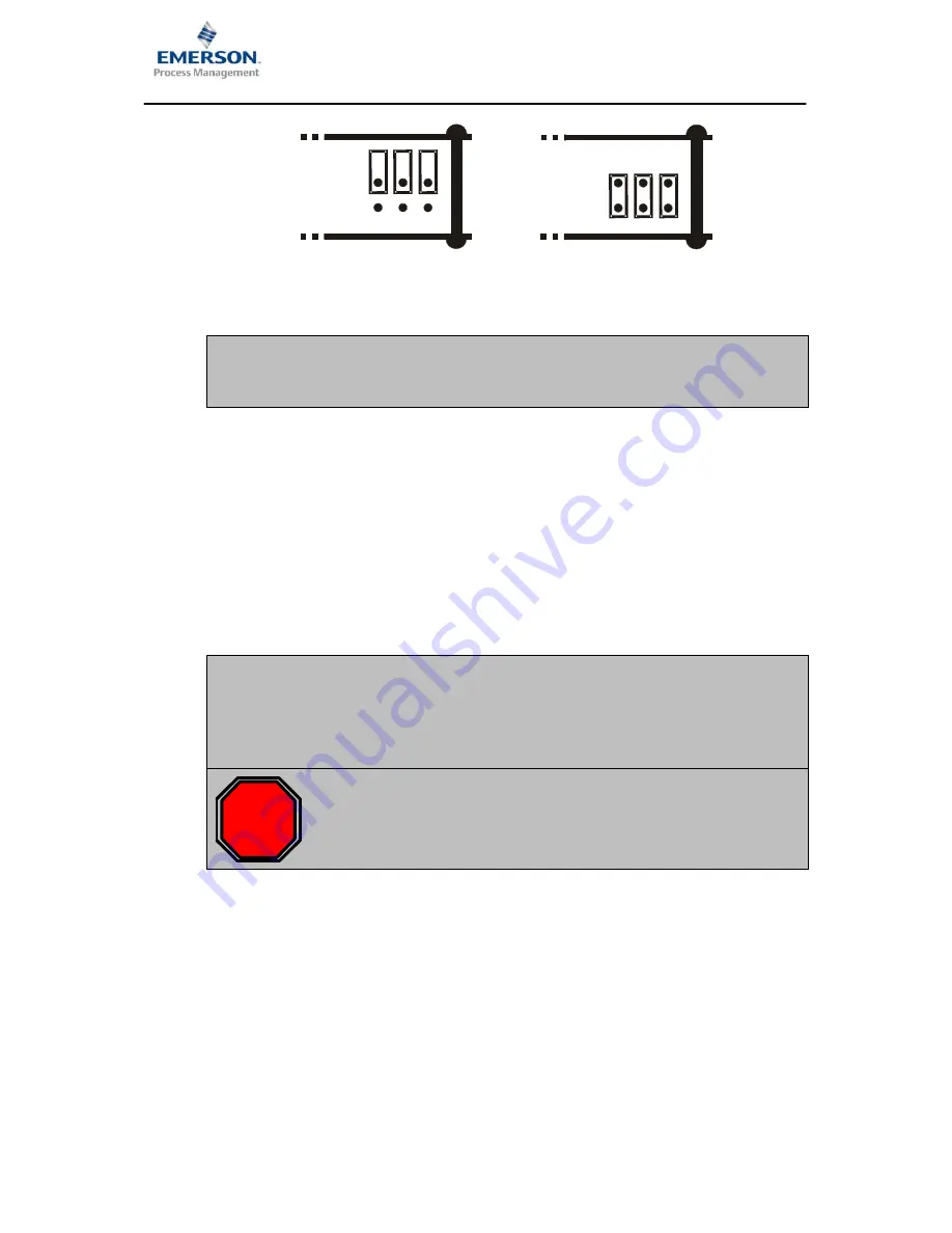
range 0 ... 20 Vss) is applied. The controller board must be removed in order to switch the signal
on the connection strip. The following points describe the procedure:
i
The reference point for the raw sensor signal from channel 1 is the connection
strip terminal z6: S), and for the raw sensor signal from channel 2 the
terminal d6: S). If these terminals are connected with terminal b10,
then the reference point is connected to system ground (GND). In this case
the terninals b22: GND and b24: GND can be used as reference point.
STOP
When working at the monitor, ensure that there is adequate protection against
electrostatic discharge. For example, wear an ESD bracelet to prevent
electrostatic discharge via the monitor electronics.


