background image

11

UL Model No.: CF144 & CF152
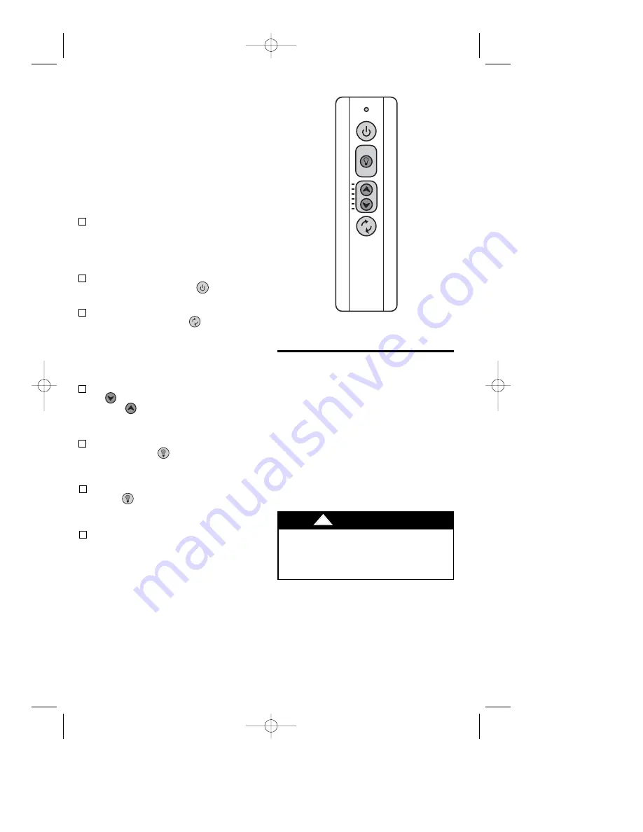
Setting Operating

Frequency of

Remote Control

1.

Slide the five switch levers in the
remote control to your choice of ON
(up) or down positions. Use a ball-point
pen or small screwdriver and slide the
levers firmly up or down.

2.

When power is restored, push and hold
the fan OFF button (    ) for 3 to 5
seconds to set the code in the receiver.

3.

If airflow is desired in the opposite
direction, press the (    ) button on the
remote control. The fan must be
operating at any speed for the reverse
button to function. The blades will turn
in the opposite direction and reverse
the airflow.

4.

To set the desired fan speed, press the
(     ) button to decrease the speed and
the (     ) to increase the speed. The
LED display will light up to indicate the
new speed selected.

5.

To turn the downlight on, press and
release the (    ) button. The light will
turn on at the light intensity previously
selected.

6.

To vary the intensity of the light, hold
the (     ) button down until the desired
light intensity is reached, then release
the button.

7.

The sixth switch marked ON and I is for
dimming control of lights: Set switch to
ON to allow for dimming of the lights.
Set switch to I for no dimming of the
lights such as for fluorescent bulbs.

Your remote control has code switches
which must be set in one of 32 possible
code combinations (Figure 16). The five
levers (numbered 1, 2, 3, 4, and 5) on the
switches are factory-set in the ON (up)
position. Change the switch settings as
follows (Figure 18):

Figure 18

Do not use water when cleaning your
ceiling fan. It could damage the motor or
the blades and create the possibility of an
electrical shock.

!

WARNING

Maintenance

IMPORTANT CARE INSTRUCTIONS

for your Ceiling Fan

Periodic cleaning of your new ceiling fan is
the only maintenance that is needed.

When cleaning, use only a soft brush or
lint free cloth to avoid scratching the finish.

Abrasive cleaning agents are not required
and should be avoided to prevent damage
to finish.

BP7407-1 44" &  52" Curva Sky  8/31/10  4:10 PM  Page 11

Summary of Contents for CURVA SKY CF144BS00

Page 1: ...4CRM00 Chrome 44 Model Numbers for Damp Locations CF144WW00 Appliance White CF144ORB00 Oil Rubbed Bronze 44 Model Numbers for Wet Locations CF152BS00 Brushed Steel CF152CRM00 Chrome 52 Model Numbers for Damp Locations CF152WW00 Appliance White CF152ORB00 Oil Rubbed Bronze 52 Model Numbers for Wet Locations Net Weight 18 5 Lbs Net Weight 19 4 Lbs BP7407 1 44 52 Curva Sky 8 31 10 4 10 PM Page 1 ...

Page 2: ...outlet boxes commonly used for support of light fixtures are not acceptable for fan support and may need to be replaced Consult a qualified electrician if in doubt 4 The fan must be mounted with the fan blades at least 7 feet from the floor to prevent accidental contact with the fan blades 5 Follow the recommended instructions for the proper method of wiring your ceiling fan If you do not know eno...

Page 3: ...12 Before assembling your ceiling fan refer to section on proper method of wiring your fan Page 7 If you feel you do not have enough wiring knowledge or experience have your fan installed by a licensed electrician WARNING Unpacking Instructions For your convenience check off boxes are provided next to each step As each step is completed place a check mark in the box This will insure that all steps...

Page 4: ...H NO LIGHT COVER PLATE E LOWER HOUSING K 50W MINI CANDELABRA HALOGEN BULBS L LOOSE PARTS BAG J 6 SPEED HANDHELD TRANSMITTER F LIGHT KIT PLATE I 6 SPEED ELECTRONIC RECEIVER C CEILING MOUNTING PLATE NOTE Place the parts from the loose parts bags in a small container to keep them from being lost PROTECTIVE PLASTIC BAG UL Model No CF144 CF152 BP7407 1 44 52 Curva Sky 8 31 10 4 10 PM Page 4 ...

Page 5: ...l Requirements Ceiling Fan Procedures How to Assemble Your Ceiling Fan Turning off wall switch is not sufficient To avoid possible electrical shock be sure electricity is turned off at the main fuse or circuit breaker box before wiring All wiring must be in accordance with National and Local codes and the ceiling fan must be properly grounded as a precaution against possible electrical shock WARNI...

Page 6: ...ted as Acceptable for Fan Support WARNING To reduce the risk of fire electric shock or personal injury mount fan to outlet box marked Acceptable for Fan Support and use screws supplied with outlet box Most outlet boxes commonly used for support of light fixtures are not acceptable for fan support and may need to be replaced Consult a qualified electrician if in doubt WARNING Turning off wall switc...

Page 7: ... not have enough electrical wiring knowledge or experience have your fan installed by a licensed electrician CAUTION To reduce the risk of electrical shock disconnect the electrical supply circuit before installing the fan light kit or receiver NOTE Make all wiring connections using wire connectors supplied Make sure that all connections are tight including ground and that no bare wire is visible ...

Page 8: ...OTOR HOUSING ASSEMBLY CEILING TRIM RING CEILING COVER SCREW HEADS 4 Figure 12 8 Check to see that all connections are tight including ground and that no bare wire is visible at the wire connectors except for the ground wire Do not operate fan until blades are in place Noise and fan damage could result WARNING FAN BLACK WIRE FAN RECEIVER BLUE WIRES SUPPLY BLACK WIRE SUPPLY RECEIVER FAN WHITE WIRES ...

Page 9: ...CF144 CF152 How to Assemble Your Light Kit Glass Shade 9 DIMPLES 3 FLAT AREA 3 GLASS BOWL Figure 14 Figure 15 How to Assemble Your No Light Cover Plate DIMPLES 3 FLAT AREA 3 COVER PLATE 1 Place the cover plate onto the lower housing aligning the three flat areas on the top flange of the cover plate with the three pins on the inside of the fan motor housing assembly Figure 15 Then turn the cover pl...

Page 10: ...eceiver is equipped with a preset memory feature If the AC supply to the receiver is powered through a wall switch when the switch is turned OFF the control will remember the light intensity and fan speed When the switch is turned back ON the light and fan will resume operation as they were prior to the switch being turned OFF REMOTE CONTROL PROCEDURES CODE SWITCHES SR600 REMOTE CONTROL BATTERY CO...

Page 11: ...ary the intensity of the light hold the button down until the desired light intensity is reached then release the button 7 The sixth switch marked ON and I is for dimming control of lights Set switch to ON to allow for dimming of the lights Set switch to I for no dimming of the lights such as for fluorescent bulbs Your remote control has code switches which must be set in one of 32 possible code c...

Page 12: ...ation with non approved equipment or unshielded cables is likely to result in interference to radio and TV reception The user is cautioned that changes and modifications made to the equipment without the approval of manufacturer could void the user s authority to operate this equipment This Class B digital apparatus meets all requirements of the Canadian Interference Causing Equipment Regulations ...

Page 13: ...r operation Or use supplied balancing kit to balance blades 4 Both lamps will 1 Loose electrical connectors 1 Shut off the branch circuit not illuminate electricity at the fuse box or breaker panel and check the receiver electrical connectors for proper installation 2 Remote control battery is weak 2 Replace the AAA remote batteries 3 The lamps are burnt out 3 Turn the electricity off and replace ...

Page 14: ...Light Kit Cover 763995 BS 763995 BS 763995 CRM 763995 CRM 763995 WW 763995 WW 763995 ORB 763995 ORB 8 52 Blade Assembly 763996 BS 763996 BS 763996 WW 763996 ORB 9 44 Blade Assembly 763998 BS 763998 BS 763998 WW 763998 ORB 10 Harness Wiring Reverse Modular Aux Capacitor 764007 764007 764007 764007 764007 764007 764007 764007 11 Handheld Transmitter 763979 763979 763979 763979 763979 763979 763979 7...

Page 15: ...rtain all parts have been removed HOW TO ORDER REPAIR PARTS WHEN ORDERING REPAIR PARTS ALWAYS GIVETHE FOLLOWING INFORMATION The model number of your Fan will be found on a label attached to the top housing For repair parts phone 1 800 654 3545 PART NUMBER NAME OF ITEM PART DESCRIPTION MODEL NUMBER BP7407 1 44 52 Curva Sky 8 31 10 4 10 PM Page 15 ...

Page 16: ...or authorized service center Your Emerson Air Comfort Ceiling Fan should be properly packed to avoid damage in transit since we will not be responsible for any such damage What Is Not Covered The glass globes and light bulbs of your ceiling fan are not covered by this warranty This warranty also does not cover any defects malfunctions or failures caused by Repairs by persons not authorized by Emer...

Reviews: