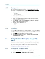
Procedure
1.
Remove security wires from the endcap and the Bracket/Cover hex head bolts that
secures the Base Enclosure if they are installed.
2.
Disable the Write Protect switch in the CPU Module to write any of the following
configuration parameters to your meter.
3.
Click the Device Variables Mapping tab. The Primary and Secondary variables are
read only and are configured for Uncorrected Flow Rate. The Third and Fourth
variable configuration choices include Pressure and Temperature.
4.
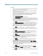
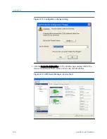
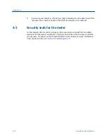
Click the Units tab (see
5.
Click the Analog Output 1 (HART) tab (see
).
6.
Click the Analog Output 2 tab. Follow the configuration instructions in the
The read only Secondary variable Content, Uncorrected Flow Rate, displays. Use the
drop-down arrow and select the (flow) Direction - Forward or Reverse. Enter a Lower
and Upper Range limit. Set the Alarm Action parameters.
a. Click Apply, after you enter the data to write the parameters to the meter.
7.
Click the Frequency/Digital Outputs tab. Follow the configuration instructions in the
(Refresh Note: If changes are made to any Source variable on this page,
apply the changes and navigate to the Guided Setup page. Navigate back to the
Manual Setup for the changes to be reflected in other Manual Setup pages).
a. Click Apply, after you enter the data to write the parameters to the meter.
8.
Click the Frequency and Digital Output 1 tab. Follow the configuration instructions
in the
.
a. Click Apply, after you enter the data to write the parameters to the meter.
9.
Click the Frequency and Digital Output 2 tab. Follow the instructions in the
to configure the Frequency and Digital Output 2 parameters.
a. Click Apply, after you enter the data to write the parameters to the meter.
10.
Click the Temperature tab. Configure the input parameters including: Source (Live
Analog or Fixed), Min and Max input limits corresponding to 4 mA and 20 mA
respectively and the Low and High alarm limits.
a. Click Apply, after you enter the data to write the parameters to the meter.
11.
Click the Pressure tab. Configure the input parameters including: Source (Live
Analog or Fixed), Min and Max input limits corresponding to 4 mA and 20 mA
respectively and the Low and High alarm limits. Select either Gage or Absolute for
the type of pressure reading desired. If a live pressure transmitter is connected,
select the type of reading the transmitter outputs. If Absolute is selected, you must
also enter the Atmospheric pressure.
a. Click Apply, after you enter the data to write the parameters to the meter.
12.
Click the Digital Input tab. The default Digital Input 1 polarity is set to Normal for
general purpose or set to Inverted when used for calibration.
a. Click Apply, after you choose the calibration data to write the parameters to the
meter.
Configuration
102
Gas Ultrasonic Flow Meter
Summary of Contents for Daniel 3410 Series
Page 8: ......
Page 122: ...Engineering drawings 112 Gas Ultrasonic Flow Meter ...
Page 123: ......
Page 124: ......
Page 125: ......
Page 126: ......
Page 139: ...Open source licenses Installation manual 125 ...


