background image

9

IMPORTANT CARE INSTRUCTIONS

for your Ceiling Fan

Periodic cleaning of your new ceiling fan is the only
maintenance that is needed.

When cleaning, use only a soft brush or lint free cloth
to avoid scratching the finish.

Abrasive cleaning agents are not required and should
be avoided to prevent damage to finish.

Maintenance

Accessories

Do not use water when cleaning your ceiling fan. It
could damage the motor or the blades and create the
possibility of an electrical shock.

This product is designed to use only those parts
supplied with this product and/or any accessories
designated specifically for use with this product by
Emerson Electric Co. Substitution of parts or acces-
sories not designated for use with this product by
Emerson Electric Co. could result in personal injury
or property damage.

The use of any other control not specifically
approved for this fan could result in fire, shock and
personal injury.

1. Ceiling Fan Light Kits (see store or catalog).

2. Downrod Extension Kits (see store or catalog).

WARNING

!

WARNING

!

WARNING

!

REV

MED

OFF

HI

LOW

U

L

D

L

®

NOTE: To prevent damage to the receiver, turn
“off” the electricity at the wall switch before
installing or removing light bulbs on the ceiling
fan or light fixture.

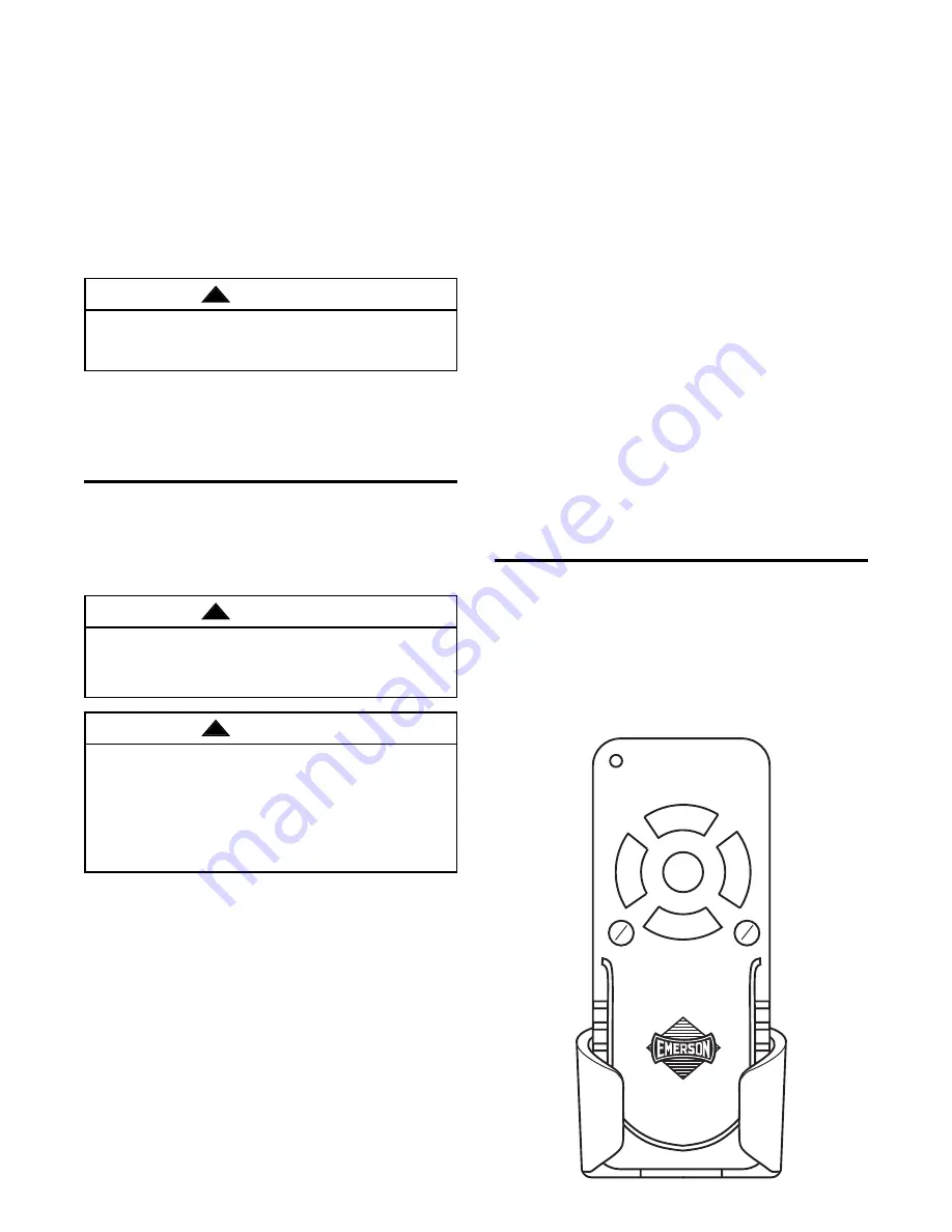
Figure 17

Operation

IMPORTANT

Fan installation must be completed, including the
installation of the fan blades, before testing of the
remote control.

Your remote control has full control of your fan and
lights (Figure 17).

NOTE: Prior to operation of the down light from
the remote control, make sure the switch on the
light is ON.

1. To set the desired fan speed, press the HI, MED,

or LOW button to operate your fan on high,
medium, or low speed.

2. To turn your fan off, press the OFF button.

3. To change the airflow direction of the fan blades,

press the REV button.

4. To turn the downlight on, press and release the D/L

button. The light will turn on at the light intensity
previously selected.

5. To turn the uplight on, press and release the U/L

button. The light will turn on at the light intensity
previously selected.

6. To vary the intensity of the light, hold the U/L or D/L

button down until the desired light intensity is
reached, then release the button.

Installation of

Storage Bracket

A storage bracket is supplied with the remote control
for holding the control unit when not in use. If you
desire to use the bracket, use the two screws
(supplied) and install it on a wall that is away from
excess heat or humidity.

Summary of Contents for Designer Remote CF759AB03

Page 1: ...o return the product to an authorized service center call 1 800 654 3545 for the address of the nearest authorized service center You will be responsible for all insurance freight or other transportation charges to our factory or authorized service center Your Emerson Air Comfort Ceiling Fan should be properly packed to avoid damage in transit since we will not be responsible for any such damage W...

Page 2: ...e not acceptable for fan support and may need to be replaced Consult a qualified electrician if in doubt 4 The downrod furnished with the fan provides the minimum recommended floor to fan blade clearance for an 8 foot ceiling 5 The fan must be mounted with the fan blades at least 7 feet from the floor to prevent accidental contact with the fan blades 6 The fan must be installed on a level ceiling ...

Page 3: ...re provided next to each step As each step is completed place a check mark in the box This will insure that all steps have been completed and will be helpful in finding your place should you be interrupted Before assembly your ceiling fan refer to section on proper method of wiring your fan page 7 If you feel you do not have enough wiring knowledge or experi ence have your fan installed by a licen...

Page 4: ...age door openers car alarms or security systems To remedy this situation simply change the combination code in your transmitter and receiver Preset Memory Feature Your Emerson remote control receiver is equipped with a preset memory feature If the electrical supply to the receiver is controlled through a wall switch when the switch is turned off the control will remember the light intensities and ...

Page 5: ... clevis pin must go through the holes in the motor coupling and the holes in the downrod Be sure to push the straight leg of the hairpin clip through the hole near the end of the clevis pin until the curved portion of the hairpin clip snaps around the clevis pin The hairpin clip must be properly installed to prevent the clevis pin from working loose Pull on the downrod to make sure the clevis pin ...

Page 6: ...al codes and the ceiling fan must be properly grounded as a precaution against possible electrical shock WARNING WARNING WARNING NOTE Remove and discard the five shipping spacers and screws from the motor hub 11 Loosely attach one blade assembly to the motor hub using two M6 x 14 captive screws with lock washers Figure 9 Make sure the screws are NOT tightened Repeat this procedure for other four b...

Page 7: ...he outlet box is installed so that the mounting surface the bottom of the outlet box is level The receiver will be damaged resulting in an inoperable fan and a possible electrical fire Hanger bracket must seat firmly against outlet box If the outlet box is recessed remove wall board until bracket contacts box If bracket and or outlet box are not securely attached the fan could wobble or fall Failu...

Page 8: ...After connecting the wires spread them apart so that the green and white wires are on one side of the outlet box and the black wire is on the other side Make sure that black antenna wire sits on top of the receiver unit OUTLET BOX BLACK SUPPLY WIRE BLACK WHITE RECEIVER WIRE BLACK FAN WIRE BLUE FAN WIRE BLUE RECEIVER WIRE ORANGE FAN WIRE YELLOW RECEIVER WIRE CEILING COVER WHITE RECEIVER WIRE WHITE ...

Page 9: ...e electricity at the wall switch before installing or removing light bulbs on the ceiling fan or light fixture Figure 17 Operation IMPORTANT Fan installation must be completed including the installation of the fan blades before testing of the remote control Your remote control has full control of your fan and lights Figure 17 NOTE Prior to operation of the down light from the remote control make s...

Page 10: ... loose the fan flanges to the motor hub are tight 4 Wire connectors inside cup assembly 4 Check to make sure wire connectors in cup rattling assembly are not rattling against each other or against the interior wall of the cup assembly WARNING Make sure main power is turned OFF 5 Screws holding blades to flanges 5 Tighten screws securely are loose 3 Fan wobbles 1 Setscrew in motor coupling is loose...

Page 11: ...11 21 6 5 20 8 9 16 13 4 1 2 3 12 11 18 10 15 14 17 7 19 Repair Parts ...

Page 12: ...Screw M5 x 6 16 9 Washer Blade 16 10 Threaded Stud 2 11 Lockwasher 2 12 Knurled Knob 2 13 Canopy Ceiling 761620 761620 33 761620 3 761620 9 761620 25 761620 26 761620 29 14 Harness Reversing 763159 763159 763159 763159 763159 763159 763159 15 Switch Housing Assembly 763158 WW 763158 ORB 763158 AB 763158 OB 763158 BS 763158 WB 763158 AW 16 Cover Coupling 762463 15 762463 16 762463 4 762463 762463 8...

Reviews: