1598024314 XR30CX VST GB r3.1 05.10.2015.doc
XR30CX
4/4
PTC probe: -55÷150°C (-67÷302°F).
Resolution: 0.1°C or 1°C or 1°F (selectable).
Accuracy (ambient temp. 25°C): ±0.7 °C ±1 digit.
Only for battery backup model:
Type of battery: 6Vdc, 1.2Ah.
Charging time: 94hours.
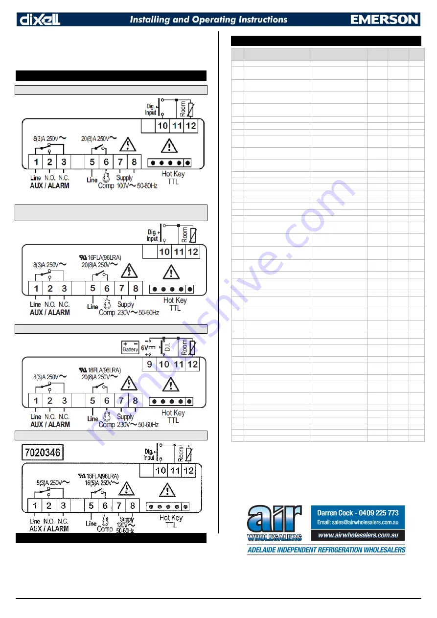
15. CONNECTIONS
15.1
XR30CX -4S1C1 (0-7020115)
15.2
XR30CX -5S1C1 WITHOUT BATTERY BACKUP (0-7020110) AND XR30CX -
5S1C7 (7020345)
15.3
XR30CX -5S1C1 WITH BATTERY BACKUP (0-7020122 AND 0-7020202)
15.4
XR30CX -5S1C7 WITHOUT BATTERY BACKUP (7020346)
16. DEFAULT SETTING VALUES
Label
Name
Range
No batt.
backup
With batt.
backup
Level
SEt Set point
LS ÷ US
-62
-82
- - -
HY Differential
[0.1
25.5°C]
[1
255°F]
[1°C]
[1°F]
[1°C]
[1°F]
Pr1
LS Minimum set point
[-100,0°C ÷ SET]
[-148°F ÷ SET]
[-63°C]
[-81°F]
[-95°C]
[139°F]
Pr2
US Maximum set point
[SET ÷ 150,0°C]
[SET ÷ 302°F]
[-30°C]
[-22°F]
[-60°C]
[-76°F]
Pr2
ot Thermostat probe calibration
[-12
12°C]
[-120
120°F]
[0°C]
[0°F]
[0°C]
[0°F]
Pr1
odS Outputs delay at start up
0 ÷ 255 min
0
0
Pr2
AC Anti-short cycle delay
0
50 min
5
5
Pr1
CCt Continuous cycle duration
0.0 ÷ 24h 00min, res. 10min
0.0
0.0
Pr2
CCS Set point for continuous cycle
[-100 ÷ 150°C]
[-148 ÷ 302°F]
[-62°C]
[-79°F]
[-82°C]
[-115°F]
Pr2
Con Compressor ON time with faulty
probe
0
255 min
60
60
Pr2
CoF Compressor OFF time with faulty
probe
0
255 min
5
5
Pr2
CH Kind of action
CL=cooling; Ht= heating
CL
CL
Pr2
CF Temperature measurement unit
°C; °F
°C
°C
Pr2
rES Resolution
in = integer; dE = dec.point
in
in
Pr2
dLY Display temperature delay
0 ÷ 20min 00s, res. 10s
0.0
0.0
Pr2
idF Interval between defrost cycles
1
120 hours
0
0
Pr1
MdF (Maximum) length for defrost
0
255 min
0
0
Pr1
dFd Displaying during defrost
rt; it; SEt; DEF
rt
rt
Pr2
dAd MAX display delay after defrost
0 ÷ 255 min
0
0
Pr2
ALC Temperature alarms configuration
rE= related to set
Ab = absolute
rE
rE
Pr2
ALU MAXIMUM temperature alarm
[Set
110°C]
[Set ÷ 230°F]
[15°C]
[59°F]
[15°C]
[59°F]
Pr1
ALL Minimum temperature alarm
[-100°C
Set]
[-148°F
Set]
[50°C]
[122°F]
[50°C]
[122°F]
Pr1
AFH Differential for temperature alarm
recovery
[0.1°C ÷ 25.5°C]
[1°F÷45°F]
[1°C]
[1°F]
[1°C]
[1°F]
Pr2
ALd Temperature alarm delay
0
255 min
0
0
Pr2
dAo Delay of temperature alarm at start
up
0
23h 50min, res. 10min
1.3
1.3
Pr2
tbA Alarm relay disabling
n; Y
Y
Y
Pr2
Aro
Alarm relay activation with power
failure
n; Y
Y
Y
Pr2
ALF
Alarm relay activation for all the
alarms
n; Y
Y
Y
Pr2
bon
Time of buzzer restart after
muting, in case of alarm duration
0 ÷ 30 min
30
30
Pr2
AoP Alarm relay polarity (oA1=ALr)
oP; CL
CL
CL
Pr2
i1P Digital input polarity
oP=opening; CL=closing
CL
CL
Pr1
i1F Digital input configuration
EAL; bAL; PAL; dor;
dEF; Htr, AUS
AUS
AUS
Pr1
did Digital input alarm delay
0 ÷ 255 min
15
15
Pr1
nPS Number of activation of pressure
switch
0 ÷ 15
15
15
Pr2
odc Compress status when open door
no; FAn; CPr; F_C
no
no
Pr2
rrd Regulation restart with door open
alarm
n; Y
Y
Y
Pr2
HES Differential for Energy Saving
[-30°C ÷ 30°C]
[-54°F÷54°F]
[1°C]
[1°F]
[1°C]
[1°F]
Pr2
Adr Serial address
0 ÷ 247
1
1
Pr2
PbC Kind of probe
PtM; PtC
PtM
PtM
Pr2
onF on/off key enabling
nU; oFF; ES
nU
nU
Pr2
rSE Real set point value
actual set
--
--
Pr2
rEL Software release
--
--
--
Pr2
Ptb Map code
--
--
--
Pr2


