1598013141 XM664K GB CLABO rev1.2 2012.01.26
XM664K
1/6
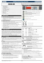
XM664K
1.
GENERAL WARNING____________________________________________________________ 1
2.
GENERAL DESCRIPTION ________________________________________________________ 1
3.
CONTROLLING LOADS__________________________________________________________ 1
4.
FRONT PANEL COMMANDS _____________________________________________________ 1
5.
SECTIONS MENU ______________________________________________________________ 2
6.
HOW TO CHANGE THE ACTIVE MAP ______________________________________________ 2
7.
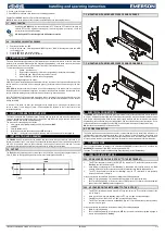
INSTALLATION AND ASSEMBLY __________________________________________________ 2
8.
ELECTRICAL CONNECTIONS ____________________________________________________ 2
9.
TTL SERIAL LINE _______________________________________________________________ 2
10.
HOW TO USE THE HOT KEY _____________________________________________________ 2
11.
ALARMS ______________________________________________________________________ 3
12.
TECHNICAL DATA ______________________________________________________________ 3
13.
CONNECTIONS ________________________________________________________________ 3
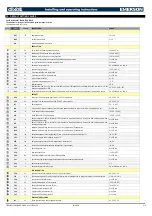
14.
DEFAULT SETTING VALUES _____________________________________________________ 4
1.
GENERAL WARNING
1.1
PLEASE READ BEFORE USING THIS MANUAL
This manual is part of the product and should be kept near the instrument for easy and quick reference.
The instrument shall not be used for purposes different from those described hereunder. It cannot be used
as a safety device.
Check the application limits before proceeding.
1.2
SAFETY PRECAUTIONS
Check the supply voltage is correct before connecting the instrument.
Do not expose to water or moisture: use the controller only within the operating limits avoiding sudden
temperature changes with high atmospheric humidity to prevent formation of condensation
Warning: disconnect all electrical connections before any kind of maintenance.
Fit the probe where it is not accessible by the End User. The instrument must not be opened.
In case of failure or faulty operation send the instrument back to the distributor (see address) with a
detailed description of the fault.
Consider the maximum current which can be applied to each relay (see Technical Data).
Ensure that the wires for probes, loads and the power supply are separated and far enough from each
other, without crossing or intertwining.
In case of applications in industrial environments, the use of mains filters (our mod. FT1) in parallel with
inductive loads could be useful.
2.
GENERAL DESCRIPTION
The XM664K is microprocessor controller suitable for medium and low temperature multiplexed cabinet
applications composed of as many as 8 sections. This makes it possible to create a LAN (local area network)
made up of the instruments which, depending on the programming, can operate as single controllers or
managing the controls which arrive from one or more sections. The XM664K is equipped with 6 relay outputs
which control the compressor, the defrost 1 and 2 (which can be either electric or with hot gas, the evaporator
fans, the lights and an ON/OFF output. It is supplied with three NTC probe inputs, one for thermostating, one for
temperature control at the end of defrost on evaporator 1 and one for end of defrost 2 control. There are also
two digital inputs which can be configured by parameters.
The two LAN outputs provide an easy connection between the various controllers while the TTL connector
programs the complete parameter list by means of a programming key called “Hot Key”.
3.
CONTROLLING LOADS
3.1
COMPRESSOR
The regulation is performed according to the temperature measured by the thermostat probe with a positive
differential from the set point: if the temperature increases and reaches set point plus differential the compressor
is started and then turned off when the temperature reaches the set point value again.
In case of fault in the thermostat probe the start and stop of the compressor are timed through parameters Con
and CoF.
3.2
DEFROST
There are three types of defrost available that can be selected with the parameter tdF: defrost with electric
heater (tdF=EL), with hot gas (tdF=in) or disabled (tdF=oFF). When defrost is over, the dripping time starts,
which is managed by the parameter Fdt.
Management of two defrosts is configured by parameters dMo, dd1, dEM and dEn. In particular:
dMo Defrost 1-2 management mode: (ind; 2-1; dEL) if dMo=ind defrost 1 e 2 managements are independent;
if dMo=2-1 activation of defrost 2 entails activation of defrost 1; if dMo=dEL activation of defrost 2 entails
activation of defrost 1 with delay set by parameter dd1;
dd1 Defrost 1 activation delay compared to defrost 2: (0 to 255 min) as previously mentioned, it describes
the activation delay of defrost 1 after activation of defrost 2 if dMo=dEL;
dEM Defrost synchronisation in LAN: (ind; Sin) if dEM=ind the end of defrosts is independent. If dEM=Sin,
the end of defrosts is synchronised;
dEn Synchronisation of local defrost end (def1 and def2): (ind; Sin) if dEM=ind the end of defrosts is
independent. If dEM=Sin, the end of defrosts is synchronised.
The start of a defrost cycle can be controlled locally (manual activation by the keyboard, digital input or at the
end of the time interval). Otherwise the command can arrive from any controller inserted in the LAN. In this last
case, the controller will start a defrost cycle and will bring it to the end following the indications present in its
programming parameters. But at the end of the cycle, it will wait for all the controllers present in the LAN to finish
before returning to normal temperature regulation.
3.3
CONTROL OF EVAPORATOR FANS
The fan control mode is selected by means of the FnC parameter:
FnC = C_n: fans will switch ON and OFF with the compressor and not run during defrost;
FnC = o_n: fans will run even if the compressor is off, and not run during defrost.
After defrost, there is a timed fan delay allowing for drip time, set by means of the Fnd parameter:
FnC = C_Y: fans will switch ON and OFF with the compressor and run during defrost;
FnC = o_Y: fans will run continuously also during defrost.
An additional parameter FSt provides the setting of temperature, detected by the evaporator probe, above which
the fans are always OFF. This is used to make sure circulation of air only if his temperature is lower than set in
FSt.
4.
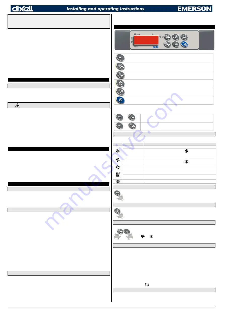
FRONT PANEL COMMANDS
To display and modify target set point; in programming mode it selects a parameter or confirm
an operation.
By holding it pressed for 3 sec when max or min temperature is displayed it will be erased.
To see the max stored temperature value.
In programming mode it browses the parameter codes or increases the displayed value.
By holding it pressed for 3s it gives access to the “Section” menu.
To see the min stored temperature value.
In programming mode it browses the parameter codes or decreases the displayed value.
By holding it pressed for 3 sec the defrost is started.
Switch ON and OFF the room light.
Keep it pressed more than 3 sec to switch ON and OFF the instrument.
KEY COMBINATIONS
+
To enter the programming mode.
+
To exit the programming mode.
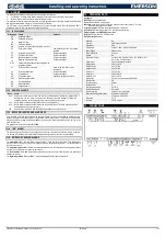
4.1
USE OF LEDS
Each LED function is described in the following table.
LED
MODE
Function
ON
Compressor enabled
Flashing
Programming phase (flashing with the LED
)
Anti-short cycle delay enabled
ON
Fans enabled
Flashing
Programming phase (flashing with the LED
)
ON
Defrost enabled
Flashing
Defrost or drip time enabled
ON
The controller is working in “ALL” mode
Flashing
The controller is working in remote virtual display mode
ON
An alarm is active
4.2
HOW TO SEE AND MODIFY THE SET POINT
1.
Push for about 3 sec the SET key: the display will show the Set point value;
2.
The measurement unit starts blinking;
3.
To change the SET value push the
o
or
n
arrows within 10 sec.
4.
To store the new set point value push the SET key again or wait 10 sec.
4.3
HOW TO START A MANUAL DEFROST
1.
Push the DEF key for more than 3 seconds and a manual defrost will start.
2.
Use the UP and DOWN keys to select the dEF1 or the dEF2.
4.4
TO ENTER IN PARAMETERS LIST “PR1”
To enter the parameter list “Pr1” (user accessible parameters) operate as follows:
1. Enter the Programming mode by pressing the SET+DOWN key for few seconds
(
and
start blinking).
2. The instrument will show the first parameter present in “Pr1”.
4.5
TO ENTER IN PARAMETERS LIST “PR2”
To access parameters in “Pr2”:
1.
Enter the “Pr1” level.
2.
Select “Pr2” parameter and press the SET key.
3.
The “PAS” flashing message will be displayed shortly, followed by “0 - -” with a flashing zero.
4.
Use
o
or
n
to input the security code in the flashing digit; confirm the figure by pressing SET. The
security code is “321“.
5.
If the security code is correct the access to “Pr2” is enabled by pressing SET on the last digit.
Another possibility is the following: after switching ON the instrument the user can push SET+DOWN keys within
30 sec.
NOTE: each parameter in “Pr2” can be removed or put into “Pr1” (user level) by pressing SET+DOWN. When a
parameter is present in “Pr1” LED
is on.
4.6
HOW TO CHANGE THE PARAMETER VALUE
1.
Enter the Programming mode.
2.
Select the required parameter with
o
or
n
.
3.
Press the SET key to display its value (measurement unit starts blinking).


