1598013141 XM664K GB CLABO rev1.2 2012.01.26
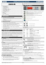
XM664K
4/6
14.
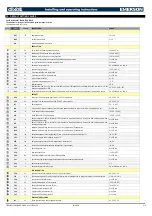
DEFAULT SETTING VALUES
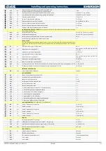
FACTORY DEFAULT PARAMETER TABLE
The indication for just one of the 5 available parameter maps is carried.
(*) Parameters visible on Pr1 level.
LABEL
VALUE
DESCRIPTION
RANGE
SET
-20
Regulation set point
LS to US
MAP
- - -
Parameter map switch
1 to 5
AtA
- - -
Alternative parameter map access
- - -
REGULATION
Hy
2,0
HY is the ON/OFF heat regulation differential
[0.1 to 25.5°C]
LS
-30
Minimum Set-Point that can be set by keyboard
[-55.0°C to SET]
US
10
Maximum Set-Point that can be set by keyboard
[SET to 150.0°C]
odS
0
Delay in minutes until switch-on before all regulation outputs are activated.
0 to 255 min
AC
1
Anti-short cycle delay of relay cold regulation output
0 to 60 min
CCt
0
Duration of continuous cycle
0.0 to 24h00min, res. 10 min
CCS
0
Continuous cycle set point
[-55.0 to 150°C]
Con
15
Time compressor ON with probe failure.
0 to 255 min
CoF
30
Time compressor OFF with probe failure.
0 to 255 min
CH
cL
Type of regulation action
CL; Ht
CF
°C
Temperature measurement unit: °C or °F
°C; °F
rES
In
Display resolution
dE; in
Lod
P1
Display probe: from P1 to P3. tEr= not used dEF=not used. If Err appears on the display, the probe is in error, or nP=not
present in parameter P1C..P3C.
nP; P1; P2; P3; tEr; dEF
dLy
0.0
Delay in minutes/ seconds of the display of temperature rise to limit effects of too quick variations of a temperature sensor.
0.0 to 24h00min, res. 10 min
DEFROST
dPA
P2
Selection of 1st defrost probe input: from P1 to P3, nP=not present.
nP; P1; P2; P3
dPb
nP
Selection of 2nd defrost probe input: from P1 to P3, nP=not present.
nP; P1; P2; P3
tdF
In
Defrosting mode
EL – in - OFF
tbO
0
Time duration of black-out/stand-by reset of intervals between defrosts (0=instant reset). If tb0 is different than 0, use
0 to 255 min
dtE
8
Probe dPA defrost 1 end temperature
[-55.0°C ÷ 50.0°C]
dtS
8
Probe dPb defrost 2 end temperature
[-55.0°C ÷ 50.0°C]
idF
8
Defrost 1 interval if EdF=in (intervals) If idF=0 defrost is forced manually only, from serial, from outside contact, from
coordinated defrost LAN.
0 to 120 hours
IdS
0
Defrost 2 interval if EdF=in (intervals) If idS=0 defrost is forced manually only, from serial, from outside contact, from
coordinated defrost LAN.
0 to 120 hours
MdF
8
Maximum duration forcing defrost 1 end if it is not cut-off before the dTE temperature.
0 to 255 min
MdS
0
Maximum duration forcing defrost 2 end if it is not cut-off before the dTS temperature.
0 to 255 min
dMo
Ind
Defrost management mode (independent, 2 force 1, 1 delayed compared to activation of 2)
Ind; 2-1; dEL
dd1
0
Defrost 1 activation delay compared to start of 2
0 to 255 min
dEM
Ind
Defrost end synchronisation in LAN (independent – synchronised)
ind; Sin
dEn
Ind
Local 1-2 defrost end synchronisation (independent – synchronised)
ind; Sin
dSd
0
Defrost delay from call
0 to 255 min
dFd
rt
Display during defrost
rt; it; Set; dEF
dAd
60
Temperature display delay after defrost blocking display.
0 to 255 min
Fdt
0
Post-defrost dripping time keeping the ventilation outputs and heat regulation stopped.
0 to 255 min
dPo
n
Defrost at switch-on (yes /no)
n; Y
dAF
0
Defrost delay after continuous cycle
0.0 to 24h00min, res. 10 min
FAN REGULATION
FPA
P2
Fan probe control input selection: from P1 to P3, nP=not present.
nP; P1; P2; P3
FnC
O-n
Fans functioning mode. C= active only with cold output ON, O= always active, n= stopped for defrost, Y= active for defrost.
C-n; O-n; C-Y; O-Y
Fnd
1
Fan switch-on delay after defrost
0 to 255 min
FSt
10
Fan block temperature on FPA fan probe
[-55.0 to 50.0°C]
FHy
1
Return differential from fans stop FSt set
[0.1 to 25.5°C]
Foo
10
Time fans on after instrument OFF
0 to 255 min
Fon
15
Time fans ON with compressor off
0 to 15 min
FoF
15
Time fans OFF with compressor off
0 to 15 min
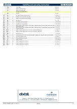
TEMPERATURE ALARMS
rAL
P1
Probe selection for HA and LA temperature alarm
nP; P1; P2; P3


