background image


XW60K 110918 V14.7 EMERSON092718 V14.7 

XW60K 

10/12 


Label 

Name 

Range 

Default 

Level 


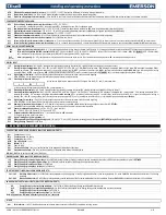
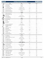
Outputs activation delay at start up 

0 to 255 min 

Pr2 


Anti-short cycle delay 

0 to 30 min 

Pr1 


Second solenoid delay 

0 to 255 sec 

Pr2 


P1-P2 percentage for regulation 

0 to 100 (100=P1 , 0=P2) 

100 

Pr2 


Solenoid ON time during fast freezing 

0.0 to 23h50min, res. 10 min 

0.00 

Pr2 


Set point for continuous cycle 

[-55.0 to 150.0°C] [-67 to 302°F] 

-5 

Pr2 


Solenoid ON time with faulty probe 

0 to 255 min 

15 

Pr2 


Solenoid OFF time with faulty probe 

0 to 255 min 

30 

Pr2 

DISPLAY


Temperature measurement unit 

°C; °F 

°F 

Pr2 


Resolution (integer/decimal point) 

in; dE 

in 

Pr1 


Keyboard display 

P1; P2; P3; P4: dtr 

P1 

Pr2 


Display temperature delay 

0.0 to 20min;00sec, res.10 sec 

1.00 

Pr2 


P1-P2 percentage for display 

1; 100 

50 

Pr2 

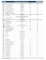
DEFROST


Defrost interval selection 

in, rtc,ond 

in 

Pr2 


Defrost type 

EL;  in 

EL 

Pr1 


Type of pump down 

Fan, F-C 

FAn 

Pr1 


Pump down time  

0to255min 

Pr1 


Probe selection for defrost termination 

nP; P1; P2; P3; P4 

P2 

Pr2 


Defrost termination temperature 

[-50.0 to 150°C] [-58 to 302°F] 

46 

Pr1 


Interval between defrost cycles 
 0= on-demand 

0 to 120 h 

Pr1 


(Maximum) length for defrost 

0 to 255 min 

30 

Pr1 


Start defrost delay 

0 to 99 min 

Pr2 


Displaying during defrost 

rt; it; SEt; dEF; dEG 

DEF 

Pr2 


MAX display delay after defrost 

0 to 255 min 

30 

Pr2 


Draining time 

0 to 60 min 

Pr2 


First defrost after start up 

n; Y 

Pr2 


Defrost delay after fast freezing 

0.0 to 23h50min, res. 10 min 

0.00 

Pr2 

FANS


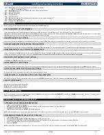
Fans operating mode 

C-n; C-y; O-n; O-y 

O_n 

Pr1 


Fans delay after defrost 

0 to 255 min 

10 

Pr1 


Differential of temperature for forced activation of 
fans 

[0 to 50°C] [0 to 90°F] 

20 

Pr2 


Fans stop temperature 

[-55.0 to 50°C] [-67 to 302°F] 

36 

Pr1 


Fan on time with solenoid off 

0 to 15 min 

Pr2 


Fan off time with solenoid off 

0 to 15 min 

Pr2 


Probe selection for fan management 

nP; P1; P2; P3; P4 

P2 

Pr2 

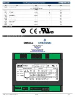
AUXILIARY THERMOSTAT


Kind of action for auxiliary relay 

CL; Ht 

CL 

Pr2 


Set Point for auxiliary relay 

[-55.0 to 150°C] [-67 to 302°F] 

32 

Pr2 


Differential for auxiliary relay 

[0.1 to 25.5°C] [1 to 45°F] 

Pr2 


Probe selection for auxiliary relay 

nP; P1; P2; P3 

nP 

Pr2 


Aux. output working during defrost 

n; Y 

Pr2 


Light on timer 

0to255min 

Pr1 

ALARMS


Probe setting for temperature alarm 

P1; P2; P3; P4 

P1 

Pr2 


Temperature alarms configuration 

rE; Ab 

Ab 

Pr2 


MAXIMUM temperature alarm 

[-55.0 to 150.0°C] [-67 to 302°F] 

230 

Pr1 


minimum temperature alarm 

[-55.0 to 150.0°C] [-67 to 302°F] 

-58 

Pr1 


Temperature alarm and fan differential 

[0.1 to 25.5°C] [1 to 45°F] 

Pr2 


Temperature alarm delay 

0 to 255 min 

15 

Pr2 

Summary of Contents for dixell XW60K

Page 1: ...ogress a continuous chill mode can be activated by holding the oUP key pressed for about 3 sec The solenoid operates to maintain the CCS set point for the time set through the CCt parameter The cycle can be terminated before the end of the set time by pressing theo UP key for 3 sec 3 3 DEFROST ON DEMAND OR RTC OPTIONAL MUST BE ORDERED Hot Gas or Electric Defrost can be managed through the tdF para...

Page 2: ...ion for the auxiliary relay Ht heating CL cooling SAA 40 230 F Set point for auxiliary relay SHy 0 25 F Differential for auxiliary output With ACH CL aux relay cut in is SAA SHy cut out SAA With ACH Ht aux relay cut in is SAA SHy cut out SAA ArP nP P1 P2 P3 P4 Probe for auxiliary relay Sdd n Y Auxiliary output working during defrost 4 5 ALARM RELAY OA3 ALR OPTIONAL By setting oA3 ALr the relay wil...

Page 3: ...arameter is also present in Pr1 ON Continuous cycle is running ON Energy saving enabled ON Light on ON Auxiliary relay on C F ON Measurement unit 6 AUTOMATIC KEYBOARD LOCK ONLY FOR T620T To avoid accidental modifications of the controller settings the T620T keyboard will be locked automatically if no key will be touched for 60 seconds The T620T will show LoC flashing for few seconds when it s lock...

Page 4: ...ming mode 2 Select the required parameter with UP or DOWN 3 Press the SET key to display its value and LED starts blinking 4 Use UP or DOWN to change its value 5 Press SET to store the new value and move to the following parameter To exit Press SET UP or wait for 15 sec without pressing any key NOTE the new programming is stored even when the procedure is exited by waiting the time out 7 8 HOW TO ...

Page 5: ...d defrosts to start together dFd Temperature displayed during defrost rt it SEt dEF rt real temperature it temperature at defrost start SEt set point dEF dEF label dAd MAX display delay after defrost 0 to 255min sets the maximum time between the end of defrost and the restarting of the real room temperature display Fdt Drip time 0 to 120min is the interval time between reaching defrost termination...

Page 6: ...ls 8 9 D I i2P Second digital input polarity oP CL oP the digital input is activated by opening the contact CL the digital input is activated by closing the contact i2F Second digital input configuration EAL bAL PAL dor dEF ES AUS Htr FAn HdF onF Sbt EAL external alarm EA message is displayed bAL serious alarm CA message is displayed PAL pressure switch alarm CA message is displayed dor door switc...

Page 7: ...th oA3 AUS and i1F AUX it switches the fourth relay 22 23 10 6 START DEFROST I1F DFR OPTIONAL It starts a defrost if there are the right conditions After the defrost is finished the normal regulation will restart only if the digital input is disabled otherwise the instrument will wait until the MdF safety time is expired 10 7 KIND OF ACTION HEATING OR COOLING I1F HTR OPTIONAL This function allows ...

Page 8: ...ments are provided with an internal check for the data integrity The EE alarm flashes when a failure in the memory data occurs In such cases the alarm output is enabled 13 3 ALARM RECOVERY Probe alarms P1 probe1 faulty P2 P3 and P4 they automatically stop 10 sec after the probe restarts normal operation Check connections before replacing the probe Temperature alarms HA LA HA2 and LA2 automatically...

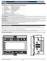
Page 9: ...n a 71x29mm panel cut out Frontal protection IP65 with frontal gasket Connections Screw terminal block 2 5 mm2 Power supply from XW60K power module Display 3 digits red LED 14 2 mm high Alarm Output buzzer Power module XW60K Case 8 DN 140X176X148 Connections Screw terminal block 2 5 mm2 heat resistant wiring and 6 3mm Faston Power supply 230Vac or 110Vac 10 or 24Vac Power absorption 6VA max Inputs...

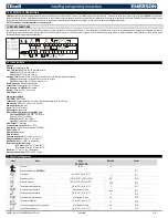
Page 10: ...30 Pr1 Start defrost delay 0 to 99 min 0 Pr2 Displaying during defrost rt it SEt dEF dEG DEF Pr2 MAX display delay after defrost 0 to 255 min 30 Pr2 Draining time 0 to 60 min 1 Pr2 First defrost after start up n Y n Pr2 Defrost delay after fast freezing 0 0 to 23h50min res 10 min 0 00 Pr2 FANS Fans operating mode C n C y O n O y O_n Pr1 Fans delay after defrost 0 to 255 min 10 Pr1 Differential of ...

Page 11: ... dEF ES Htr FAN ONF AUS LHT dor Pr1 Digital input alarm delay 0 to 255 min 0 Pr1 Number of activation of pressure switch 0 to 15 15 Pr2 Compress and fan status when open door no FAn CPr F_C F C Pr2 Regulation restart with door open alarm n Y yes Pr2 Light off during energy saving status n Y no Pr2 Differential for Energy Saving 30 to 30 C 54 to 54 F 0 Pr2 Current hour read only after first set up ...

Page 12: ...r1 Evaporator probe display read only Pr1 Third probe display read only Pr1 Fourth probe display read only Pr1 Current set point read only Pr1 Software release read only Pr2 Map code read only Pr2 18 CERTIFICATIONS 19 FOR WARRANTY AND OTHER INFORMATION 1065 Big Shanty Road Suite 100 Kennesaw GA 30144 www emerson com Support Phone 770 425 2724 select option 2 SolutionsTechSup Emerson com Sales solu...

Reviews: