XW60K 110918 V14.7 EMERSON092718 V14.7
XW60K
5/12
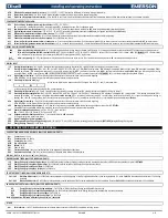
odS
Outputs activation delay at start up:
(0 to 255min) this function is enabled at the initial start up of the instrument and inhibits any output activation for the period of time set in the parameter.
AC
Anti-short cycle delay:
(0 to 50min) minimum interval between the solenoid stop and the following restart.
AC1
2
nd
solenoid delay at start up
(0to255s) Used only with oA3 or oA4 = cP2 Time interval between the switching on of the first solenoid and the second one. OPTIONAL
rtr
Percentage of the second and first probe for regulation:
(OPTIONAL)
(0 to 100; 100=P1, 0=P2) allows regulation according to the percentage of the first and second probe, per the following formula (
rtr
(P1-
P2)/100 = P1).
CCt
Solenoid ON time during continuous cycle:
(0.0 to 24h00min, res. 10min) the maximum length of the continuous cycle. Solenoid stays on without interruption during
CCt
time. This is useful, for instance,
when the room is filled with new products.
CCS
Set point for continuous cycle:
(-55 to 150°C; -67 to 302°F) the set point used during the continuous cycle. Use P1 probe.
Con
Solenoid ON time with faulty probe:
(0 to 255min) time during which the solenoid is active in case of faulty thermostat probe. With
Con=0
solenoid is always OFF.
CoF
Solenoid OFF time with faulty probe:
(0 to 255min) time during which the solenoid is OFF in case of faulty thermostat probe. With
CoF=0
solenoid is always active.
DISPLAY
CF
Temperature measurement unit:
(°C; °F)
°C
= Celsius;
°F
= Fahrenheit.
WARNING:
When the measurement unit is changed the SET point and the values of the parameters
HY
,
LS
,
US
,
ot
,
ALU
and
ALL
have to be checked and modified (if necessary).
rES
Resolution (for °C):
(in=1°C; dE=0.1°C) allows decimal point display only in °C
rEd
Keyboard display:
(P1; P2, P3, P4, SET, dtr) it selects which probe is displayed by the Keyboard.
P1
= Thermostat probe;
P2
= Evaporator probe;
P3
= Third probe (;
P4
= Fourth probe,
SET
= set point;
dtr
=
percentage of visualization.
dLY
Display delay:
(0 to 20min: 00s; res. 10s) when the temperature increases, the display is updated of 1°C or 1°F after this time.
dtr
Percentage of the second and first probe for visualization when rEd=dtr:
(0 to 99; 100=P1, 0=P2) if
rEd=dtr
it allows to set the visualization according to the percentage of the first and second probe, as for
the following formula (
dtr
(P1-P2)/100 + P2).
DEFROST
EdF
Defrost mode (only for controller with RTC):
-
rtC:
Real Time Clock mode
. Defrost time follows
Ld1 to Ld6
parameters on workdays and
Sd1 to Sd6
on holidays.
-
in:
interval mode
. The defrost starts when the time
idf
is expired.
-
ond:
On Demand Defrost ® (manually initiate first def for the control to learn the defrost cycle)
tdF
Defrost type:
(EL; in)
EL
= electrical heater;
in
= hot gas.
Pdt
Type of pump down: Fan:
only the fan will run during pump down
-
F-C:
fan and liquid line solonoid will be open during pump down
Pdn
Pump down duration:
(0to255min) The pump down starts before defrost. During the pump down the fans (and LLS) are forced to be active for the Pdn time, before the defrost starts.
With Pdn = 0 the pump down is disabled
dFP
Probe selection for defrost termination:
(nP; P1; P2; P3; P4)
nP
= no probe;
P1
=return air probe;
P2
= evaporator probe;
P3
=discharge air probe;
P4
= configurable probe.
dtE
Defrost termination temperature:
(-55 to 50°C; -67 to 122°F) (enabled only when
EdF=Pb
) sets the temperature measured by the evaporator probe, which causes the end of defrost.
idF
Interval between defrost cycles:
(0 to 120hours) determines the interval of time between two defrost cycles. If iDF = 0, and EdF = ond, the On-Demand Defrost is selected
ndF
(Maximum) length for defrost:
(0 to 255min) when
P2P=n
, (not evaporator probe: timed defrost) it sets the defrost duration. When
P2P=Y
(defrost end based on temperature) it sets the maximum length for
defrost as a safety.
dSd
Start defrost delay:
(0 to 99min) this is useful when different defrost start times are necessary to avoid defrosts to start together.
dFd
Temperature displayed during defrost:
(rt; it; SEt; dEF)
rt
= real temperature;
it
= temperature at defrost start;
SEt
= set point;
dEF
= “
dEF
” label.
dAd
MAX display delay after defrost:
(0 to 255min) sets the maximum time between the end of defrost and the restarting of the real room temperature display.
Fdt
Drip time:
(0 to 120min) is the interval time between reaching de
frost termination temperature and the restoring of the control’s normal operation. This time allows the evaporator to elimina
te water on the
evaporator before the next cycle.
dPo
First defrost after start-up:
(n; Y)
n
= after the
idF
time,
Y
= immediately. Also First defrost after a power outage.
dAF
Defrost delay after continuous cycle:
(0.0 to 24h00min, res. 10min) time interval between the end of the fast freezing cycle and the following defrost related to it.
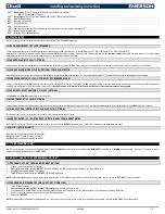
FANS
FnC
Fans operating mode:
(C-n; o-n; C-Y; o-Y)
C-n
= runs with the solenoid, OFF during defrost;
o-n
= continuous mode, OFF during defrost;
C-Y
= runs with the solenoid, ON during defrost;
o-Y
= continuous
mode, ON during defrost.
Fnd
Fans delay after defrost:
(0 to 255min) interval between the end of a defrost cycle and evaporator fans start.
FCt
Temperature differential to avoid fan short cycles:
(0 to 59°C; 0 to 90°F) (N.B.:
FCt=0
means function disabled) if the difference of temperature between the evaporator and the room probes is higher than
FCt
value, the fans will be switched on.
FSt
Fans stop temperature:
(-55 to 50°C; -67 to 122°F) setting of temperature, detected by evaporator probe, above which fans are always OFF.
Fon
Fan ON time:
(0 to 15min) with
Fnc=C_n
or
C_Y
, (fan activated in parallel with LLS) it sets the evaporator fan ON cycling time when the LLS is closed. With
Fon=0
and
FoF≠0
the fan are always off, with
Fon=0
and
FoF=0
the fan are always off.
FoF
Fan OFF time:
(0 to 15min)
With
FnC=C_n
or
C_Y
, (fan activated in parallel with LLS) it sets the evaporator fan off cycling time when the LLS is closed.
With
Fon=0
and
FoF≠0
the fan are always off, with
Fon=0
and
FoF=0
the fan are always off.
FAP
Probe selection for fan management:
(nP; P1; P2; P3; P4)
nP
= no probe;
P1
=return air probe;
P2
= evaporator probe;
P3
=discharge air probe;
P4
= configurable Probe
AUX THERMOSTAT CONFIGURATION (terms. 22-23) IF OA3 = AUS: OPTIONAL i.e. Heater
ACH
Kind of regulation for auxiliary relay:
(Ht; CL)
Ht
= heating;
CL
= cooling.
SAA
Set Point for auxiliary relay:
(-55.0 to 150.0°C; -67 to 302°F) it defines the temperature set point to switch auxiliary relay. Can be used for door / glass heaters.
SHY
Differential for auxiliary output:
(0.1 to 25.5°C; 1 to 45°F) intervention differential for auxiliary output set point.
•
ACH=CL
, AUX Cut in is [
SAA+SHY
]; AUX Cut out is
SAA
.
•
ACH=Ht
, AUX Cut in is [
SAA
–
SHY]
; AUX Cut out is
SAA
.
ArP
Probe selection for auxiliary:
(nP; P1; P2; P3; P4)
nP
= no probe, the auxiliary relay is switched only by the digital input;
P1
= Probe 1 Do Not Use (Return air probe);
P2
= Probe 2 Do Not Use (evaporator
probe);
P3
= Probe 3 (discharge probe);
P4
= configurable Probe 4.
Sdd
Auxiliary relay off during defrost:
(n; Y)
n
= the auxiliary relay operates during defrost.
Y
= the auxiliary relay is switched off during defrost.
LHt
Light timer
: (0-255 min)
The time that the light will stay on after pressing the light switch on the keyboard, or after closing the door.
ALARMS
ALP
Probe selection for alarm:
(nP; P1; P2; P3; P4)
nP
= no probe, the temperature alarms are disabled;
P1
= Probe 1 (Return Air probe);
P2
= Probe 2 (evaporator probe);
P3
= Discharge Air Probe);
P4
= Fourth probe.
ALC
Temperature alarms configuration:
(Ab; rE)
Ab
= absolute temperature, alarm temperature is given by the
ALL
or
ALU
values.
rE
= temperature alarms are referred to the set point. Temperature alarm is
enabled when the temperature exceeds the [
SET+ALU
] or [
SET-ALL
] values.
ALU
MAXIMUM temperature alarm:
•
If
ALC=Ab
: [ALL to 150.0°C or ALL to 302°F]
•
If
ALC=rE
: [0.0 to 50.0°C or 0 to 90°F]
when this temperature is reached the alarm is enabled, after the
ALd
delay time.
ALL
Minimum temperature alarm:
•
If
ALC=Ab
: [-55°C to ALU; -67 to ALU]
•
If
ALC=rE
: [0.0 to 50.0°C or 0 to 90°F]
when this temperature is reached the alarm is enabled, after the
ALd
delay time.


